
Laser sensor for self-mixing interferometry with increased detection range

a laser sensor and detection range technology, applied in lasers, semiconductor lasers, instruments, etc., can solve the problems of short detection range, limited detection range of this sensor, and main drawback of laser sensors, etc., and achieve the limitation of short detection range of vcsel-based smi laser sensors to short-range applications

Active Publication Date: 2010-06-03
TRUMPF PHOTONIC COMPONENTS GMBH
View PDF9 Cites 40 Cited by
  • Summary
  • Abstract
  • Description
  • Claims
  • Application Information

AI Technical Summary

Benefits of technology

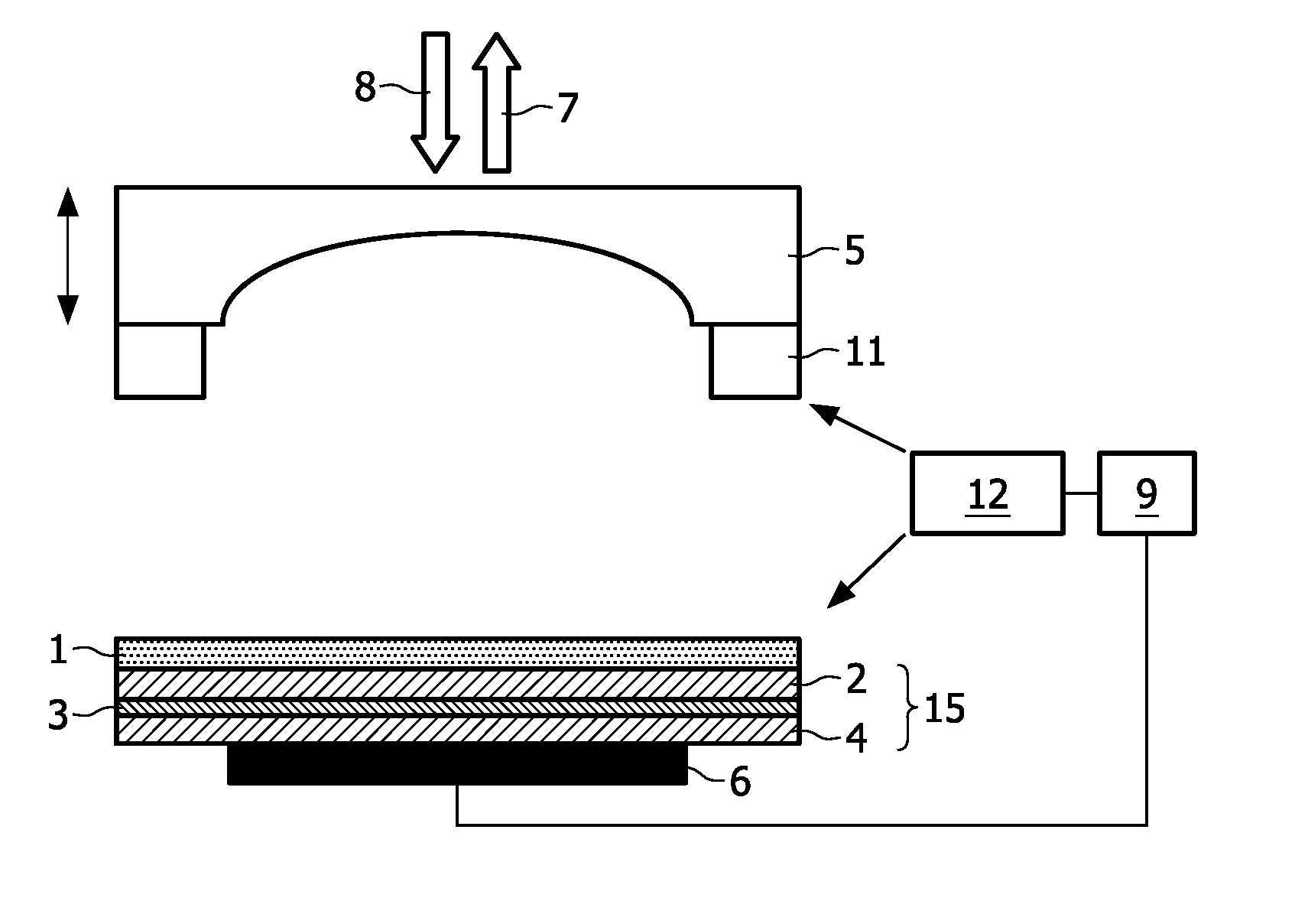
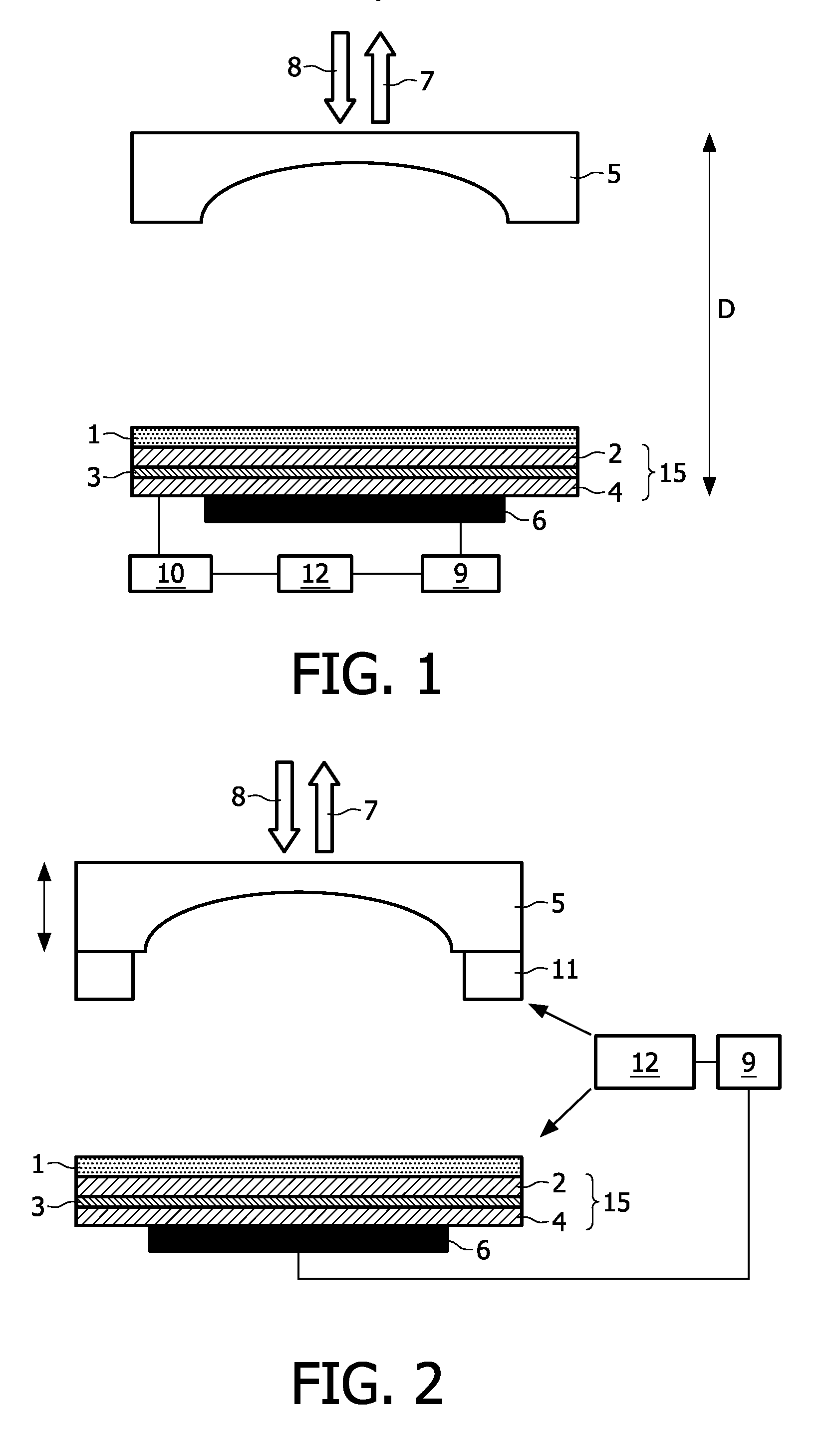
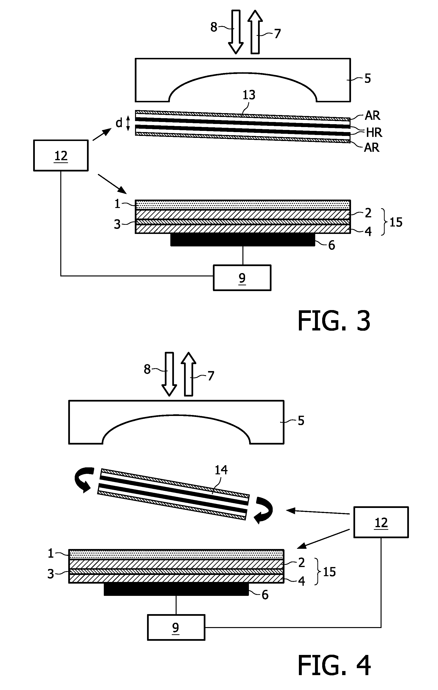
The present invention provides an SMI laser sensor that exceeds the detection range of VCSEL-based sensors and can still be manufactured in a low-cost production process. The laser sensor is based on a vertical external cavity surface emitting laser (VECSEL) with an increased coherence length, which results in a significantly increased coherence length and power density as compared with a VCSEL. The increased coherence length allows the laser sensor to have a larger detection range, which can be used in various applications such as automotive safety or motion detection. The VECSEL is designed in a similar manner to a VCSEL and can be produced in a low-cost production process. The patent text also describes the construction of a VECSEL and the use of a wavelength scanning or wavelength tuning element for distance measuring or wavelength tuning. The patent also describes the use of multiple VECSELs in an array for higher laser powers and the design of the external mirrors to deflect a portion of the laser radiation.

Problems solved by technology

Due to the short coherence length of the VCSEL and the low output power density, the detection range of this sensor is limited to several millimeters.
This short detection range is a main drawback of laser sensors with VCSELs as laser light sources.
However, the short detection range limits the application of such VCSEL-based SMI laser sensors to short-range applications.

Method used


Image

  • Laser sensor for self-mixing interferometry with increased detection range
  • Laser sensor for self-mixing interferometry with increased detection range
  • Laser sensor for self-mixing interferometry with increased detection range

Examples


Embodiment Construction

[0029]In the following examples of the proposed laser sensor, the VECSEL consists of a VCSEL layer structure 15 formed by an electrically pumped gain medium 3

[0030](InGaAs quantum wells embedded in GaAs) embedded between two Distributed Bragg Reflectors (DBR) 2, 4, which form an inner cavity of the laser. The lower DBR 4 is highly reflective (reflectivity preferably >99.5%) for the lasing wavelength, while the upper DBR 2 has a smaller reflectivity in order to allow feedback from the external cavity. One of the DBRs is p-doped and the other n-doped so as to allow efficient current feeding into the gain region. In this example, the lower DBR 4 with the higher reflectivity is p-doped and the upper DBR 2 is n-doped. Principally, however, doping in the reversed order is also possible.

[0031]The operating current for current injection into the gain medium 3 is provided by an appropriate power source 10 which, in the embodiment of the proposed laser sensor of FIG. 1, is connected to a sens...


PUM


Abstract

The present invention relates to a laser sensor for self-mixing interferometry. The laser sensor comprises at least one semiconductor laser light source emitting laser radiation and at least one photodetector (6) monitoring the laser radiation of the laser light source. The laser light source is a VECSEL having a gain medium (3) arranged in a layer structure (15) on a front side of a first end mirror (4), said first end mirror (4) forming an external cavity with an external second end mirror (5). The proposed laser sensor provides an increased detection range and can be manufactured in a low-cost production process.

Description

FIELD OF THE INVENTION[0001]The present invention relates to a laser sensor for self-mixing interferometry, comprising at least one semiconductor laser light source emitting laser radiation and at least one photodetector monitoring the laser radiation of the laser light source.[0002]Laser sensors based on self-mixing interferometry (SMI) provide the possibility of measuring velocities, vibrations and distances and thus cover a wide range of applications. SMI laser sensors make use of the effect that laser light, which is scattered back from a target object and re-enters the laser cavity, interferes with the resonating radiation and thus influences the output properties of the laser. When the laser is operated not too far above the laser threshold, the response to the back-coupled light is linear, and the resulting output power or frequency variations contain traceable information on the movement or distance of the target object with respect to the sensor. The laser output signal, wh...

Claims


Application Information

Patent Timeline
Patent Type & Authority Applications(United States)
IPC IPC(8): G01B11/02G01B9/02H01S5/14H01S5/183
CPCH01S5/0262H01S5/183H01S5/142H01S5/141H01S5/0028G01B9/02092H01S3/1062H01S5/0264H01S5/0427H01S5/0607H01S5/187
Inventor BAIER, JOHANNESMOENCH, HOLGER
Owner TRUMPF PHOTONIC COMPONENTS GMBH
Learn More