
PCM type interface

a type of interface and type technology, applied in the field of pcm type interfaces, can solve the problems of more complex control methods and delay in transmission, and achieve the effect of increasing the number of possible ways

Inactive Publication Date: 2010-06-03
STMICROELECTRONICS SA +1
View PDF11 Cites 0 Cited by
  • Summary
  • Abstract
  • Description
  • Claims
  • Application Information

AI Technical Summary

Benefits of technology

This configuration enhances the flexibility and efficiency of data exchange in duplex mode, reducing transmission delays and resource requirements, and allowing for more versatile system utilization, particularly in PCM-based systems.

Problems solved by technology

This generates transmission delays, requires the providing of additional resources in functional unit 12 (particularly buffers), and necessitates more complex means of control in order to operate the system under the different possible utilization scenarios.

Method used


Image

  • PCM type interface
  • PCM type interface
  • PCM type interface

Examples


Embodiment Construction

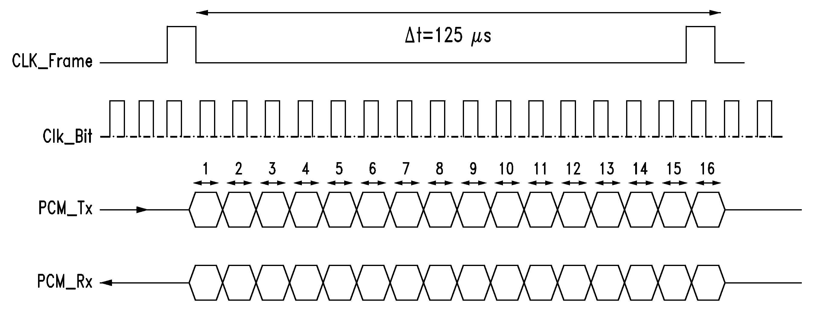
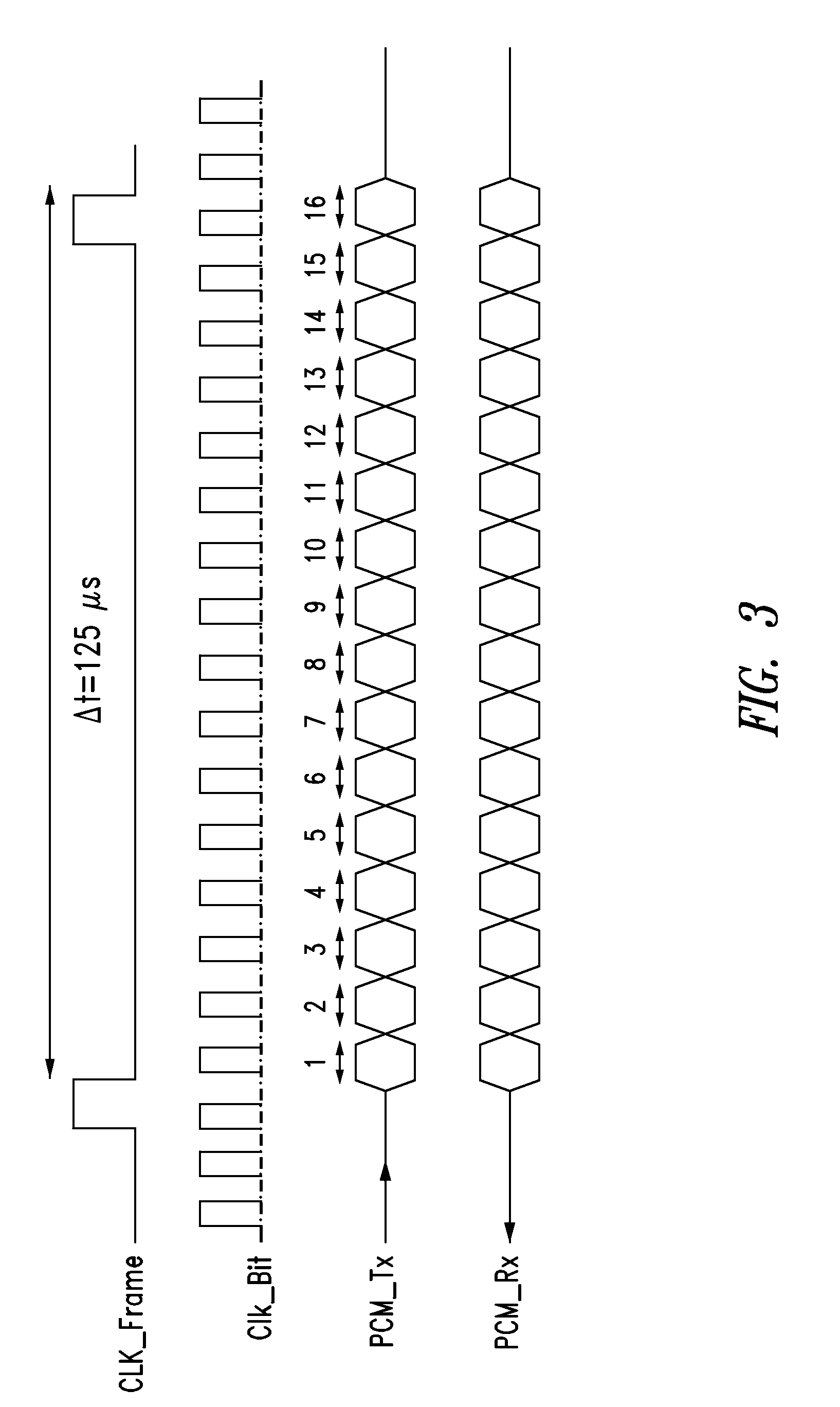
[0044]In FIG. 3, time diagrams for signals CLK_Frame, CLK_Bit, PCM_Tx and PCM_Rx are represented, one below the other, for the case of a single channel PCM signal. In this example, each signal sample is encoded into 16 bits. The 16 bits of a sample of the PCM_Tx or PCM_Rx signal are sent between two pulses of the clock signal CLK_Frame, which means during the period Δt of a CLK_Frame clock cycle.

[0045]In the case where the frequency of the CLK_Frame signal is equal to 8 kHz, in other words when Δt equals 125 μs, the frequency of the CLK_Bit signal for such a single channel signal can be equal to 128 kHz. In the figure, the numbers 1 to 16 refer to the 16 bits of a sample successively transmitted during the period Δt.

[0046]In FIG. 4, the same time diagrams as in FIG. 3 are represented, still showing a frequency of the CLK_Frame signal equal to 8 kHz and 16 bits per sample, but for the case of a PCM signal with N channels.

[0047]In this case, the period Δt between two pulses of the CLK...


PUM


Abstract

An interface device having a first and second data terminal configured for the communication of data in duplex mode, with one of the first and second data terminals always assigned to each direction of the communication, the first and second data terminals configurable during operation such that, in a first mode of operation, the first data terminal is configured to send but not to receive data and the second data terminal is configured to receive but not send data, while in a second mode of operation the first data terminal is configured to receive but not to send data and the second data terminal is configured to send but not to receive data.

Description

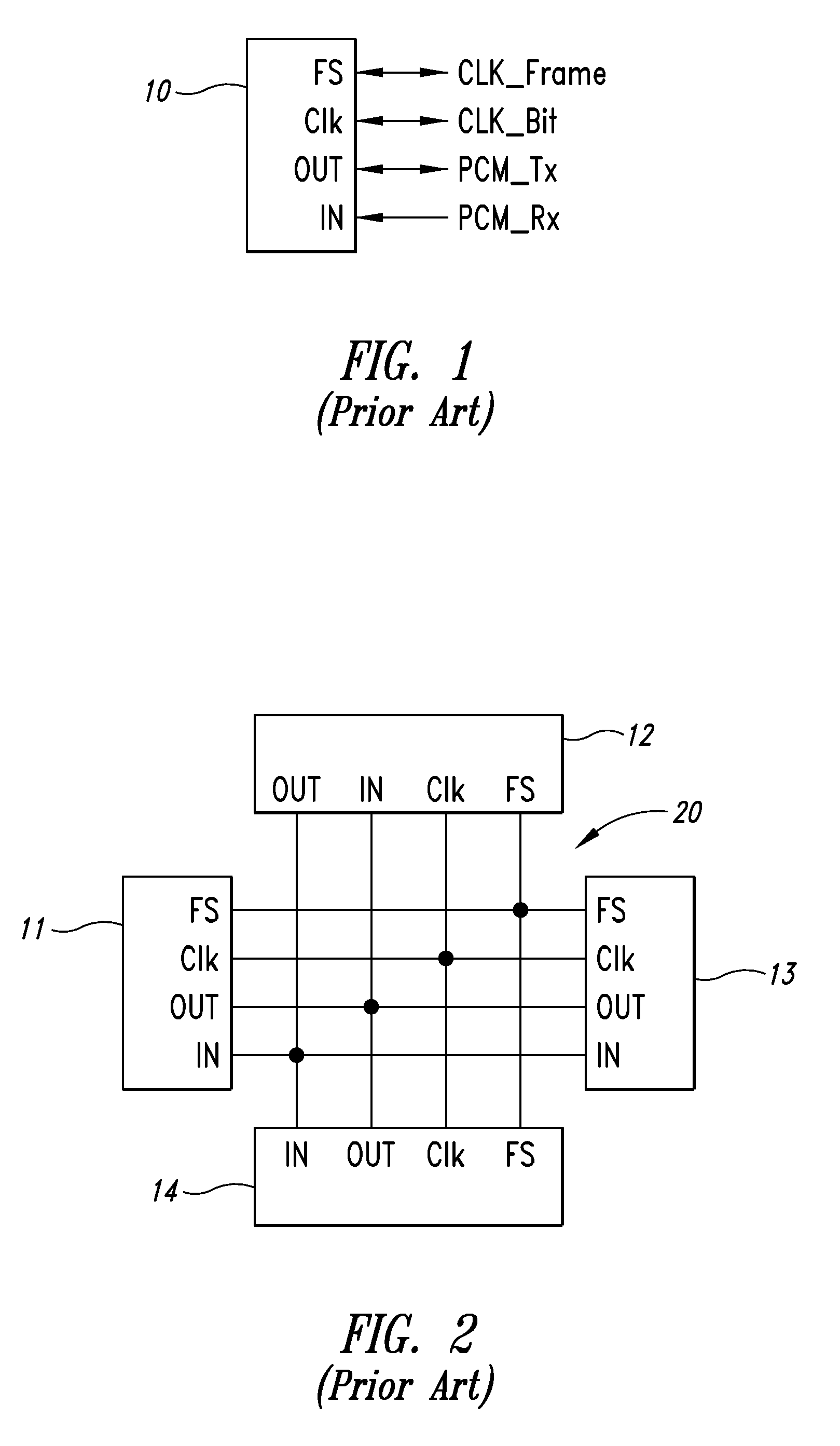
FIELD OF THE INVENTION[0001]The present invention concerns PCM type interfaces (where PCM stands for “Pulse Code Modulation”).DESCRIPTION OF THE RELATED ART[0002]PCM is a method for synchronous multiplexing and encoding, in which audio signals are represented in the form of a digital data signal multiplexed by time division multiple access (TDMA). A PCM signal is therefore a digital signal obtained by temporal multiplexing of multiple analog voice signals sampled using the same reference for sampling.[0003]As is shown in FIG. 1, a prior art PCM interface of a functional unit 10 comprises:[0004]a first clock terminal Clk and a second clock terminal FS, each configured to receive or to send a bit-level synchronizing clock signal CLK_Bit and a frame-level synchronizing clock signal CLK_Frame; and,[0005]a data input terminal IN and a data output terminal OUT, respectively configured to receive a data signal PCM_Rx and to send a data signal PCM_Tx in duplex mode.[0006]In telephony applic...

Claims


Application Information

Patent Timeline
Patent Type & Authority Applications(United States)
IPC IPC(8): H04B7/212
CPCH04B14/04H04M1/6066H04L7/0008
Inventor IANOS, ANCA-MARINAPESENTI, PAOLO
Owner STMICROELECTRONICS SA
Learn More