Apparatus and method of visualizing multi-energy imaging data

a multi-energy imaging and data technology, applied in tomography, instruments, nuclear engineering, etc., can solve the problems of misleading results, essentially limited decomposition procedures, and limited material specification

Active Publication Date: 2010-06-03
GENERAL ELECTRIC CO
View PDF26 Cites 20 Cited by
  • Summary
  • Abstract
  • Description
  • Claims
  • Application Information

AI Technical Summary

Benefits of technology

[0019]According to one aspect of the invention, an imaging system includes an x-ray source configured to emit a beam of x-rays toward an object to be imaged, a detector configured to receive x-rays that are attenuated by the object, a data acquisition system (DAS) operably coupled to the detector, and a computer operably coupled to the DAS and pro

Problems solved by technology

Because the space of linear attenuation curves can be described as a two-dimensional manifold plus a residual difference which is too small to be measured under current CT technology, this decomposition procedure is essentially limited to the specification of only two materials.
However, although a three material decomposition represents a dramatic improvement over a two material decomposition, which itself is a dramatic improvement over conventional single energy imaging, a three material combination is nevertheless a simplific

Method used


Image

  • Apparatus and method of visualizing multi-energy imaging data
  • Apparatus and method of visualizing multi-energy imaging data
  • Apparatus and method of visualizing multi-energy imaging data

Examples


Embodiment Construction

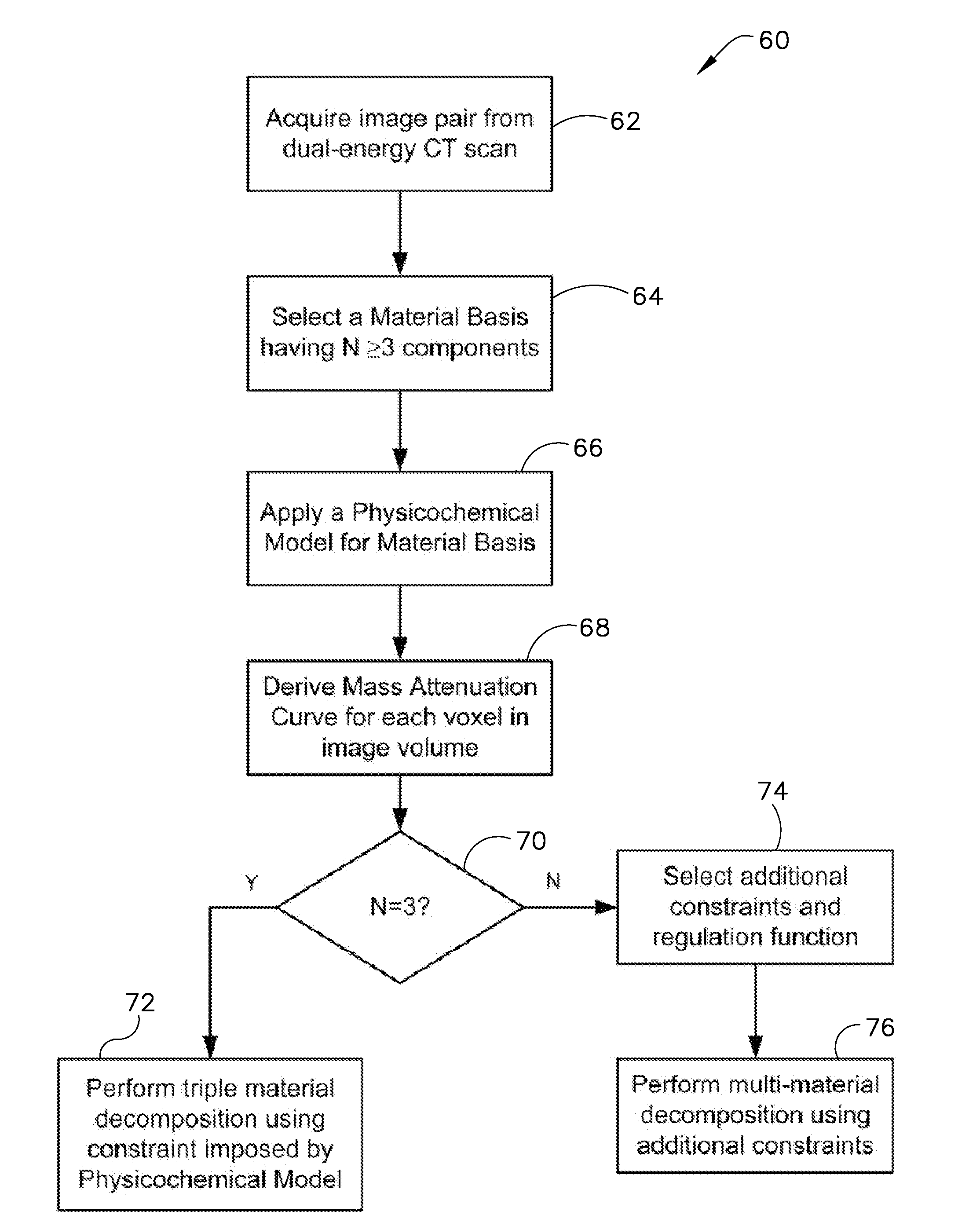
[0036]As noted above, conventional dual-energy CT scanner processing does not evaluate the composition of ‘N≧3 ’ materials in a material component mix, and is thus generally limited to a decomposition in only two materials (i.e., N=2). In an exemplary aspect of the disclosed method, the capabilities of the dual-energy CT scanner are expanded from producing a material-decomposed image pair to producing a material-decomposed image triplet. The image triplet is obtained by assuming that the various mixtures of substances and tissue types found in the human body have physicochemical properties substantially equivalent to those of what is herein denoted as an ‘ideal material solution.’ This can also be done by using a model for the excess free energy of the mixture. Using this equivalence provides a model for the density of an imaged material mixture, where the model complements the image information provided by the conventional CT data. Under this model, the mass attenuation curve of a ...


PUM


Abstract

An imaging system includes an x-ray source configured to emit a beam of x-rays toward an object to be imaged, a detector configured to receive x-rays that are attenuated by the object, a data acquisition system (DAS) operably coupled to the detector, and a computer operably coupled to the DAS and programmed to obtain scan data with two or more incident energy spectra, decompose the obtained scan data into at least three basis materials, generate an image of one of the at least three basis materials using the decomposed scan data, and replace at least one pixel in the image using decomposed data of another of the at least three basis materials.

Description

CROSS-REFERENCE TO RELATED APPLICATIONS[0001]The present application is a continuation-in-part of and claims priority to U.S. patent application Ser. No. 12 / 315,184 filed Nov. 28, 2008, and also claims priority to U.S. Provisional Application 61 / 264,286 filed Nov. 25, 2009.BACKGROUND[0002]The subject matter disclosed herein relates to computed tomography (CT) imaging systems and, in particular, to a multi-material decomposition method and visualization method using dual energy x-ray sources for CT imaging systems.[0003]Typically, in CT imaging systems, an x-ray source emits a fan-shaped or a cone-shaped x-ray beam toward a subject or object, such as a patient or a luggage item positioned on a support. The x-ray beam impinges on a detector assembly at the far side of the subject, comprising a plurality of detector modules, where the intensity of the x-ray beam detected is a function of the attenuation of the x-ray beam by the subject. In known “third generation” CT systems, the x-ray...

Claims


Application Information

Patent Timeline
IPC IPC(8): G06K9/00
CPCG06T11/006A61B6/507G06T2211/408
Inventor THOMSEN, BRIAN WILLIAMMENDONCA, PAULOBHOTIKA, RAHUL
Owner GENERAL ELECTRIC CO
Why Eureka
Try Eureka