

Endoscope system with scanning function
a scanning function and endoscope technology, applied in endoscopes, medical science, surgery, etc., can solve the problems of difficult fine scanning, etc., and achieve the effect of high image quality
- Summary
- Abstract
- Description
- Claims
- Application Information
AI Technical Summary
Benefits of technology
Problems solved by technology
Method used
Image

Examples
first embodiment
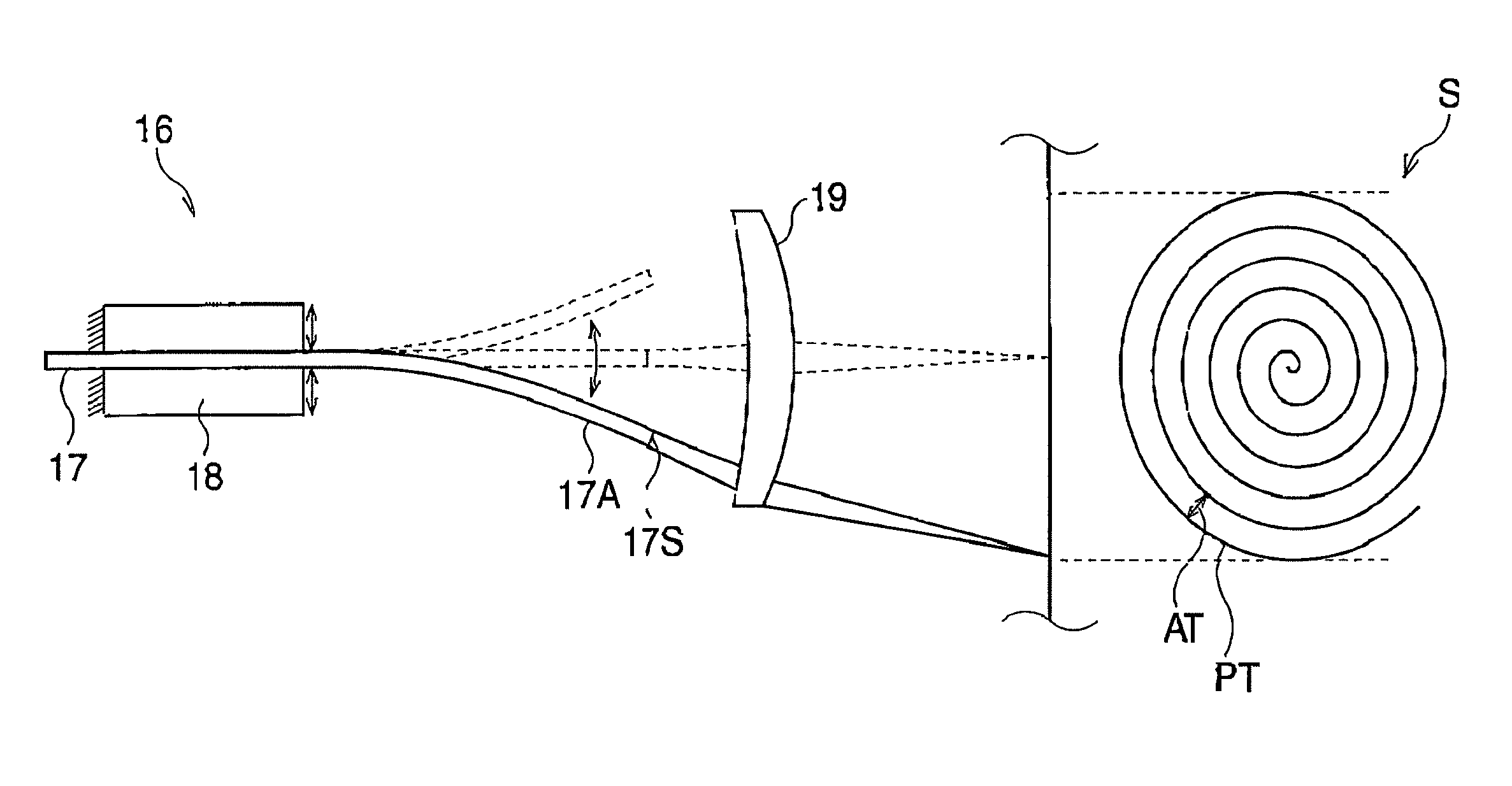
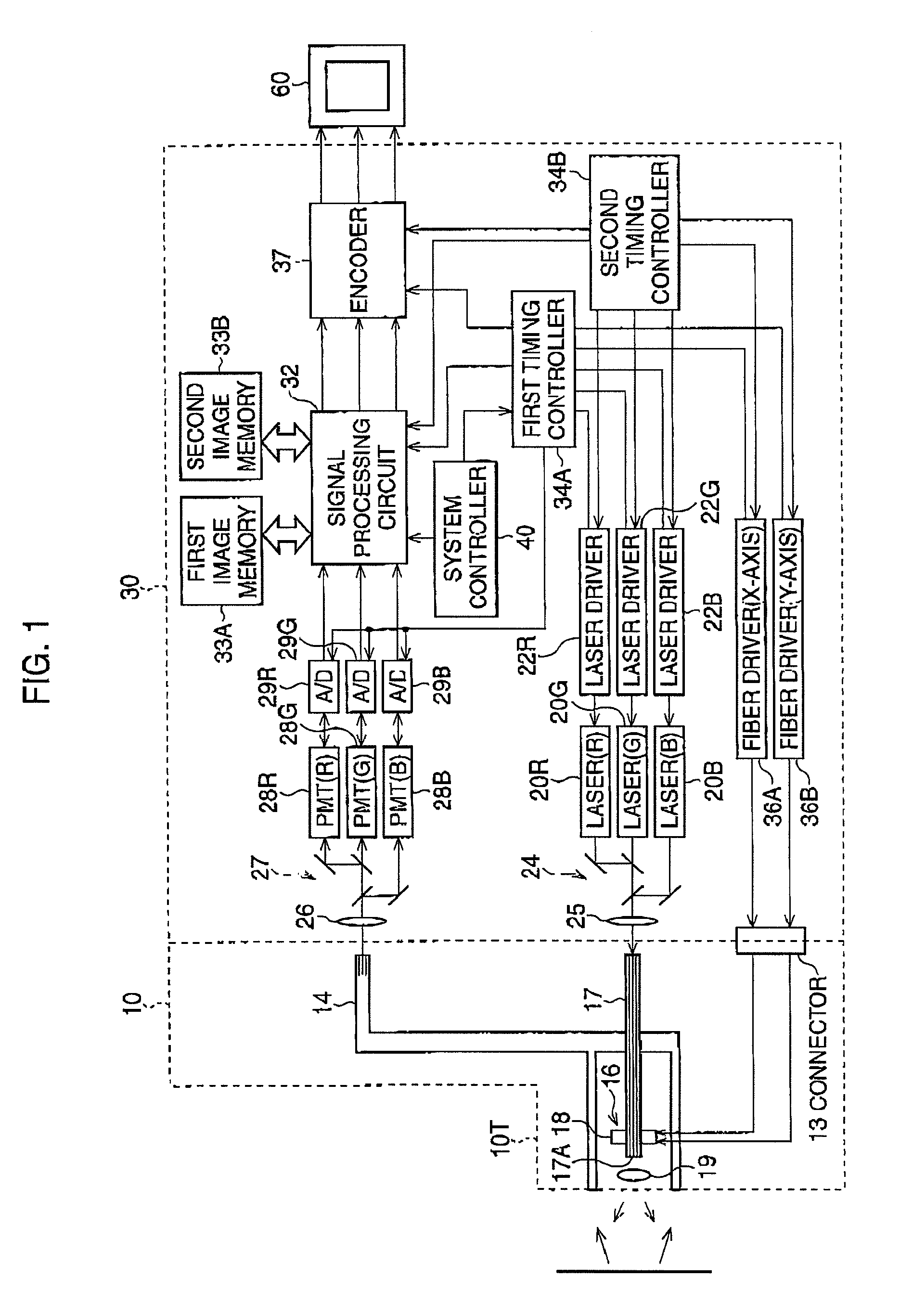
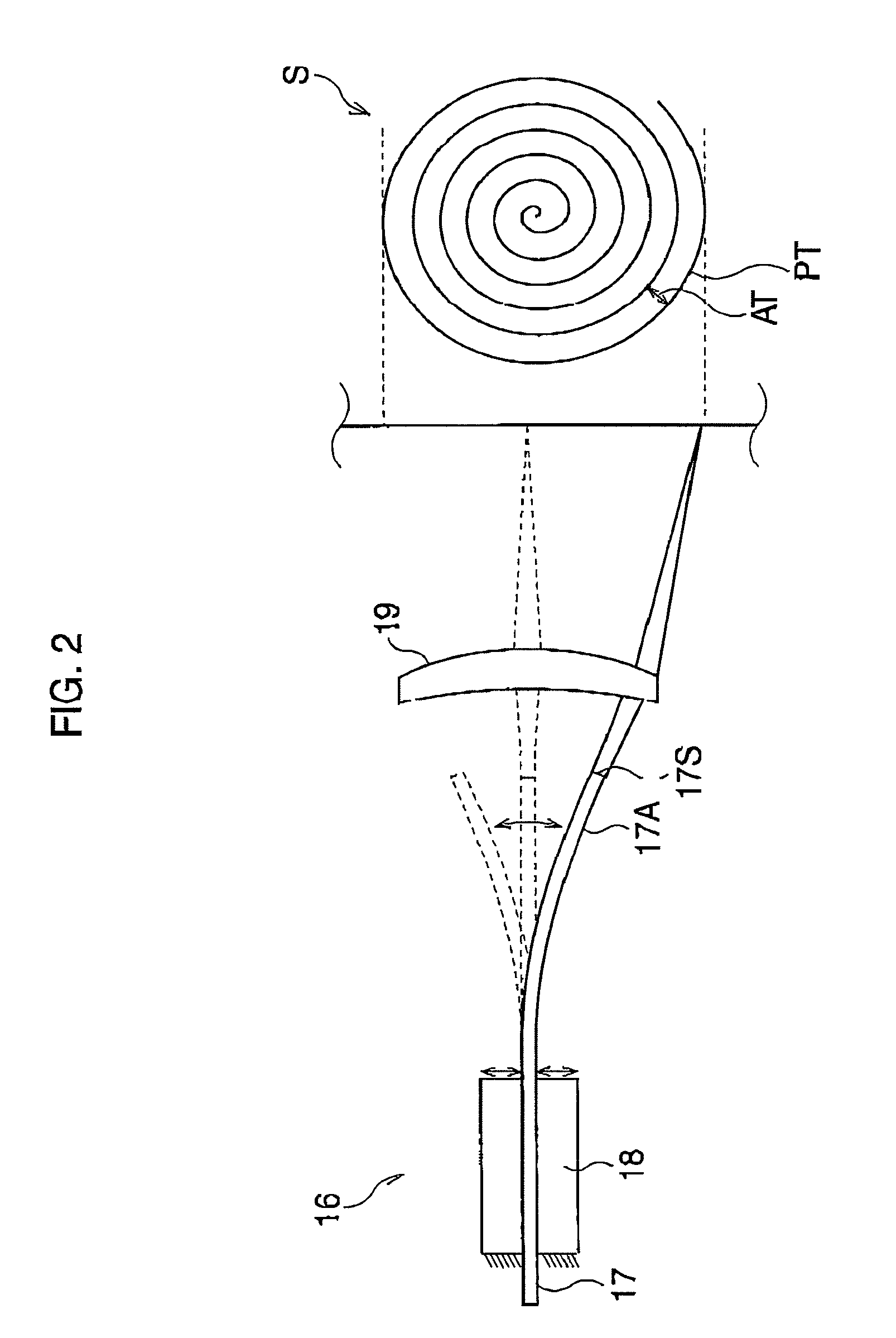
[0033]FIG. 1 is a block diagram of an endoscope system according to a FIG. 2 is an illustration of the scanning optical fiber, scanning unit, and spiral scan pattern.
[0034]The endoscope system is equipped with a processor 30 and an endoscope 10 that includes a scanning fiber 17 and an image fiber 14. The single mode type of scanning fiber 17 transmits illumination light, whereas the image fiber 14 transmits light that is reflected off an observation target S such as tissue. The endoscope 10 is detachably connected to the processor 30, and the monitor 60 is connected to the processor 30.
[0035]The processor 30 has three lasers 20R, 20G, and 208, which emit red, green, and blue light, respectively. The lasers 20R, 20G, and 20B are driven by three laser drivers 22R, 22G, and 22B, respectively. The simultaneously emitted red, green, and blue light is collected by half-mirror sets 24 and a collection lens 25. Consequently, white light enters into the scanning fiber 17 and travels to the ...
second embodiment
[0068]FIG. 7 is a block diagram of an endoscope system according to the
[0069]A video processor 30′ is equipped with a timing controller 34′ that outputs synchronizing signals to the laser drivers 22R, 22G, and 22B; and the fiber drivers 36A and 36B. The timing controller 34′ carries out a spiral scan and a circular scan alternately. A correction data memory 41′ stores luminance data associated with an amount of illumination light.
[0070]FIG. 8 is a view showing scan lines that have been drawn in one frame interval. FIG. 9 is a view showing the driving voltage level during scanning. In the second embodiment, a spiral scan and a circular scan are carried out alternately during the entire frame interval, i.e., from a scanning starting point to a scanning endpoint.
[0071]FIG. 10 is a flowchart of a brightness adjustment process performed by the system controller 40. FIG. 11 is a timing chart indicating the amount of illumination light and luminance data.
[0072]In Step S201, it is determine...
third embodiment
[0078]FIG. 12 is a flowchart of an image adjustment process according to the
[0079]In Step S301, it is determined whether a present scanning line is an odd line. When the present scanning line is an odd line, detected image-pixel data is stored in the first image memory 33A (S303). On the other hand, when the present scanning line is an even line, detected image-pixel data is stored in the second image memory 33B (S302). When one revolution's scan is finished (S304), the first image memory 33A or the second image memory that has been used to store the image-pixel data is switched to the other memory (S305). In Step S306, an average luminance level D0n is calculated from one odd-interval scan line's worth of luminance data, and it is determined whether the average luminance level D0n is outside of a tolerance range. The tolerance range corresponds to the range between T1 to T2 shown in FIG. 11.
[0080]When the average luminance level D0n is outside of the tolerance range, image processi...
PUM
 Abstract
Description
Claims
Application Information