Multifunctional cardiac pacemaker system

a pacemaker and multi-functional technology, applied in the field of multi-functional cardiac pacemaker systems, can solve the problems of increased surgery duration, increased risk of infections, obstruction of fixation, blood flow,

Inactive Publication Date: 2010-06-03
TKEBUCHAVA TENGIZ
View PDF27 Cites 6 Cited by
  • Summary
  • Abstract
  • Description
  • Claims
  • Application Information

AI Technical Summary

Benefits of technology

[0014]Implementations of this aspect of the invention may include one or more of the following features. The first cardiac lead comprises a flexible hollow tube comprising a proximal end and a distal end and the hollow tube defines a lumen extending between the proximal and distal ends and is dimensioned to house a conductive lead connecting the pulse generator to the first and second electrodes. The second electrode comprises a cone-shaped body having a sharp tip end for penetrating the apex of the right cardiac ventricle and a cavity containing the second fixation means. The second fixation means comprise first and second foldable wings, a screw-driven mechanism for folding and unfolding the first and second foldable wings and the stylet is inserted through the lumen and is attached to the screw-driven mechanism and is used to activate the screw-driven mechanism and to push the second electrode into the left cardiac ventricle. The first cardiac lead may further comprise an ultrasound transmitter at its distal end and an ultrasound receiver at its proximal end and the ultrasound transmitter is located and oriented so that it transmits ultrasound waves that pass through the cardiac left ventricle and left atrium and are modulated by the cardiac rhythm prior to being received b

Problems solved by technology

The implantation of multiple electrodes into the heart increases the duration of the surgery and the risk for infections.
However, cannulation of the coronary sinus may cause blood flow, obstructions and problems with the fixation of the lead.
Furthe

Method used


Image

  • Multifunctional cardiac pacemaker system
  • Multifunctional cardiac pacemaker system
  • Multifunctional cardiac pacemaker system

Examples


Embodiment Construction

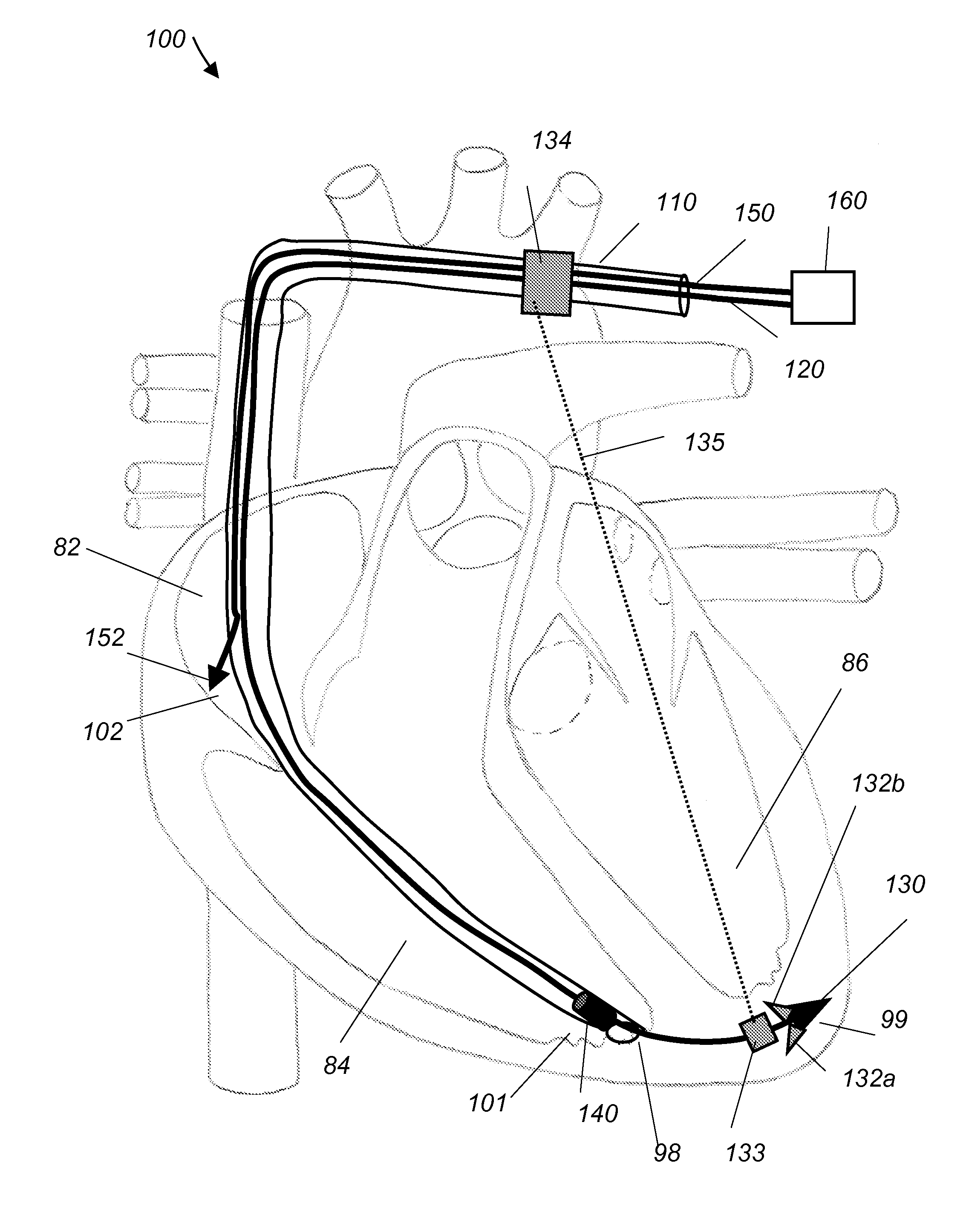
[0029]Referring to FIG. 4, pacemaker system 100 includes a pacemaker device 160, cardiac leads 120 and 150, guide catheter 110, an ultrasound transmitter 133 and an ultrasound receiver 134. Cardiac lead 150 is implanted in the right atrium 82 and comprises an electrode 152 at its distal end that is actively fixed into location 102 of the right atrium 82. Cardiac lead 120 is implanted in the right ventricle (RV) 84 and comprises a first electrode 140 (RV electrode) and a second electrode 130 (left ventricle (LV) electrode) at its distal end. First electrode 140 is positioned at a location 101 close to the apex 98 of the right ventricle 84. Second electrode 130 perforates the apex 98 of the right ventricle 84 and is actively fixed into the apex 99 of the left ventricle 86. This three electrode configuration 152, 140, 130, and their corresponding implantation locations 102, 101 and 99 are selected so that the artificial pacemaker system 100 simulates the efficacy and delivery locations...


PUM


Abstract

A pacemaker system 100 includes a pacemaker device 160, cardiac leads 120 and 150, guide catheter 110, an ultrasound transmitter 133 and an ultrasound receiver 130. Cardiac lead 150 is implanted in the right atrium (RA) 82 and includes an electrode 152 at its distal end that is actively fixed into location 102 of the right atrium 82. Electrode 152 is used for pacing of the RA. Cardiac lead 120 is implanted in the right ventricle (RV) 84 and includes two separate electrodes. A first electrode 140 is actively fixed into location 101 close to the apex 98 of the right ventricle 84 and is used for pacing, sensing and/or defibrillating of the RV. A second electrode 130 perforates the apex 98 of the right ventricle 84 and is actively fixed into the apex 99 of the left ventricle (LV) 86. Electrode 130 is used for pacing, sensing and/or defibrillating of the LV.

Description

CROSS REFERENCE TO RELATED CO-PENDING APPLICATIONS[0001]This application claims the benefit of U.S. provisional application Ser. No. 61 / 118,887 filed on Dec. 1, 2009 and entitled CARDIAC PACEMAKER SYSTEM FOR BIVENTRICULAR PACING, which is commonly assigned, and the contents of which are expressly incorporated herein by reference.FIELD OF THE INVENTION[0002]The present invention relates to a multifunctional cardiac pacemaker system and a method of treating cardiac pathologies with this multifunctional cardiac pacemaker system.BACKGROUND OF THE INVENTION[0003]The human heart is a muscular organ that pumps blood throughout the blood vessels.[0004]The heart is located between the lungs in the middle of the chest, behind and slightly to the left of the sternum. A double-layered membrane called the pericardium surrounds the heart like a sac. The outer layer of the pericardium surrounds the roots of the heart's major blood vessels and is attached by ligaments to the spinal column, diaphrag...

Claims


Application Information

Patent Timeline
IPC IPC(8): A61N1/362
CPCA61N1/3622
Inventor TKEBUCHAVA, TENGIZ
Owner TKEBUCHAVA TENGIZ
Why Eureka
Try Eureka