Method for enhancement of a wind plant layout with multiple wind turbines

a technology of wind turbines and layouts, applied in the field of wind turbines, can solve the problems of increasing the viewing the wind plant, and achieve the effects of reducing increasing the power output and minimizing the wake loss of individual wind turbines

Active Publication Date: 2010-06-03
GENERAL ELECTRIC CO
View PDF1 Cites 44 Cited by
  • Summary
  • Abstract
  • Description
  • Claims
  • Application Information

AI Technical Summary

Benefits of technology

[0009]In accordance with aspects of the invention, a method is provided for determining a wind turbine layout in a wind power plant wherein a plurality of wind turbines generate a combined power output. The method includes identifying any manner of constraint of a wind power plant site, and defining at least one region in the site for placement of a plurality of wind turbines. The wind state at the region is assessed by any conventional method, such as historical data, wind assessment programs, and the like. Once the initial wind state is determined, the method includes predicting actual wind conditions at the possible locations in the region identified for placement of wind turbines by modeling the wind state with wake effects at the respective locations, the wake effects resulting from cumulative placement of other wind turbines at the various locations in the region, or in other regions at the site. Individual wind turbine configurations and locations within the region are then determined as a function of the calculated actual wind conditions at each individual location to increase power output of the individual wind turbines. The selection of turbine configuration includes selection of a turbine hub height that minimizes wake loss of the individual wind turbines taking into consideration the predicted actual wind conditions at the turbine locations.
[0010]The present invention also encompasses a wind power plant that is configured in accordance with the principles embodied herein. The wind power plant includes a power plant site comprising at least one region having a plurality of wind turbines at respective turbine locations configured for generation of a combined power output. The wind turbines have a location and a configuration relative to each other determined as a function of actual wind conditions at each turbine location, the actual wind conditions being a function of wind state at the site and wake effects at the respective turbine locations resulting from cumulative placement of other wind turbines in the region. The wind turbines within the region have varying hub heights so as to increase power output of the individual wind turbines for the determined actual wind conditions at the respective turbine location, the varying hub heights determined as a function of actual wind conditions at the respective wind turbine locations calculated by modeling the wind state at the region with wake effects that result from cumulative placement of other wind turbines at various locations in the region. The varying turbine hub heights are selected to decrease wake loss of the individual wind turbines.

Problems solved by technology

The commercially available wind plant programs, and the methodology described in the WO 2008092462 publication, have the disadvantage that they view the wind plant as a single power producing unit subjected to an overall site condition, rather than a cluster of individual turbines subjected to unique wind conditions.
The conventional methods do not allow for consideration of the unique wind conditions experienced by each individual wind turbine within the plant, and thus do not consider that the individual turbine output can be increased by tailoring individual wind turbine characteristics, such as hub height, turbine types, and so forth, to the actual wind conditions experienced at each wind turbine location.

Method used


Image

  • Method for enhancement of a wind plant layout with multiple wind turbines
  • Method for enhancement of a wind plant layout with multiple wind turbines
  • Method for enhancement of a wind plant layout with multiple wind turbines

Examples


Embodiment Construction

[0019]Reference now will be made in detail to embodiments of the invention, one or more examples of which are illustrated in the drawings. Each example is provided by way of explanation of the invention, not limitation of the invention. In fact, it will be apparent to those skilled in the art that various modifications and variations can be made in the present invention without departing from the scope or spirit of the invention. For instance, features illustrated or described as part of one embodiment, can be used with another embodiment to yield a still further embodiment. Thus, it is intended that the present invention covers such modifications and variations as come within the scope of the appended claims and their equivalents.

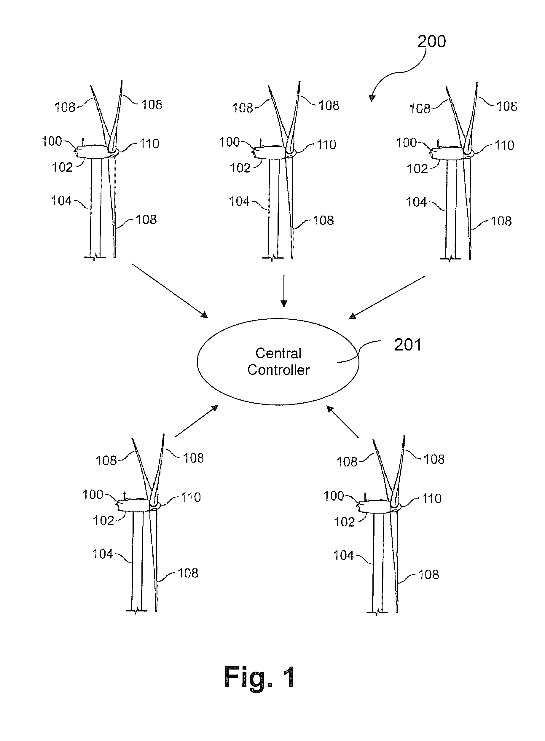
[0020]As shown in FIG. 1, a wind power plant 200 includes a number of wind turbines 100. Each turbine 100 generally comprises a nacelle 102 housing mounted atop a tower 104. The nacelle 102 generally includes a generator, controller, and other associated e...


PUM


Abstract

The layout and configuration of wind turbines in a wind power plant includes identifying constraints of a power plant site and defining at least one region in the site for placement of a plurality of wind turbines. The wind state at the region in the site is determined. An actual wind condition at the various possible wind turbine locations within the site is determined by modeling the wind state with wake effects at the respective wind turbine locations, the wake effects resulting from cumulative placement of other wind turbines at various locations in the region. Individual wind turbine configuration and location within the region is then selected as a function of the actual wind conditions that each of the individual wind turbine locations to optimize power output of the individual wind turbines. The selection of turbine configuration includes selection of a turbine hub height that minimizes wake loss of the individual wind turbines as a function of the actual wind conditions predicted for the turbine location.

Description

FIELD OF THE INVENTION[0001]The present invention is directed generally to wind turbines, and more particularly to a method for enhancing an initial layout of multiple wind turbines in a wind plant.BACKGROUND[0002]Wind turbines are receiving increased attention as an environmentally safe and relatively inexpensive alternative energy source. With this growing interest, considerable efforts have been made to develop wind turbines and wind turbine plants that are reliable, efficient, and cost-effective.[0003]Placement of wind turbines within a wind power plant has traditionally been performed with the single objective of maximizing overall energy production from the plant. For example, in designing the wind plant, wind turbines are initially placed at locations within the geographic boundaries of the plant having the highest winds based on a wind resource grid. A wind resource grid can be generated using commercially available wind resource assessment or modeling software such as WindP...

Claims


Application Information

Patent Timeline
Patent Type & Authority Applications(United States)
IPC IPC(8): G06G7/48
CPCF03D1/006F03D7/043F03D7/048F05B2260/82F05B2270/20F05B2270/32F05B2260/84G06F17/50G06F2217/16Y02E10/723F03D9/005F05B2240/96F05B2270/321F03D7/026F03D13/30F03D9/257G06F2111/10G06F30/00Y02E10/72F05B2270/204
Inventor GUNDLING, CHRIS HENRY
Owner GENERAL ELECTRIC CO
Why Eureka
Try Eureka