Traveling drive unit for working vehicle

a technology for working vehicles and drive units, which is applied in the direction of axle units, toothed gearings, special data processing applications, etc., can solve the problems of shortening the service life of the pump itself, premature abrasive wear and damage to seals and bearings, and preventing dry idle operations more stably

Active Publication Date: 2010-06-10
NIHON KENKI CO LTD
View PDF8 Cites 31 Cited by
  • Summary
  • Abstract
  • Description
  • Claims
  • Application Information

AI Technical Summary

Benefits of technology

[0009]In view of the above-discussed problem with the prior art, it is an object of the present invention to provide a traveling drive unit for working vehicle, which is arranged to turn on and off a lubricant circulation pump according to vehicle speeds thereby preventing dry idling operations of the lubricant circulation pump and ensuring longer service life of the pump.
[0012]With the arrangements just described, when the rotational speed of a wheel (vehicle speed) is lower than a predetermined reference speed, for example, the electric motor is turned on to drive the lubricant circulation pump, thereby forcibly circulating lubricant oil pooled in a wheel mounting case. Thus, for example, the temperature of lubricant oil circulating to and from the wheel mounting case through circulation paths can be lowered by way of an oil cooler, and lubricant oil of a lower temperature can be supplied to a reduction gear mechanism within the wheel mounting case, ensuring higher performance quality in lubricative and cooling effects.
[0013]On the other hand, when the rotational speed of the wheel (vehicle speed) becomes higher than a reference speed in such a situation, lubricant oil in the wheel mounting case behaves in such away as to stick on the entire inner peripheral surfaces of the wheel mounting case under the influence of centrifugal force, disabling the lubricant circulation pump to suck in lubricant oil. In such a case, the motor control means turns off the electric motor to suspend the operation of the lubricant circulation pump, preventing dry idling operations of the lubricant circulation pump to protect seals and bearings of the lubricant circulation pump against abrasive wear and damages, ensuring longer service life of the pump and at the same time preventing deteriorations of lubricant oil.
[0020]In this case, the electric motor is turned on to forcibly circulate lubricant oil when a temperature of lubricant oil detected from the temperature sensor is higher than a predetermined reference temperature and a vehicle speed detected from the speed sensor is lower than a predetermined reference speed. Further, the electric motor is turned off when a detected temperature is lower than the reference temperature or when a detected vehicle speed is higher than the reference speed, thereby preventing the lubricant circulation pump from being put in a dry idling operation.
[0024]With the arrangements just described, temperatures of lubricant oil detected from the left and right temperature sensors are compared to check out if there is a clear difference between left and right temperatures, permitting to make a judgment easily as to whether or not there is an abnormality or trouble in the left or right temperature sensor. Particularly, abnormalities in sensors can be easily diagnosed from a difference between left and right temperatures of lubricant oil in the case of a traveling drive unit for a dump truck since left and right drive wheels are rotationally driven independently of each other by way of a reduction gear mechanism or the like.
[0028]With the arrangements just described, the lubricant circulation pump is prevented from being put in a dry idling operation, for example, due to deficiency of lubricant oil, thus preventing dry idling operations more stably by the use of a pressure sensor and speed sensor.

Problems solved by technology

Besides, in such a case, the lubricant circulation pump is put in a dry idling operation, which would cause premature abrasive wear and damages to seals and bearings of the lubricant circulation pump more and as a result would shorten the service life of the pump itself.

Method used


Image

  • Traveling drive unit for working vehicle
  • Traveling drive unit for working vehicle
  • Traveling drive unit for working vehicle

Examples


first embodiment

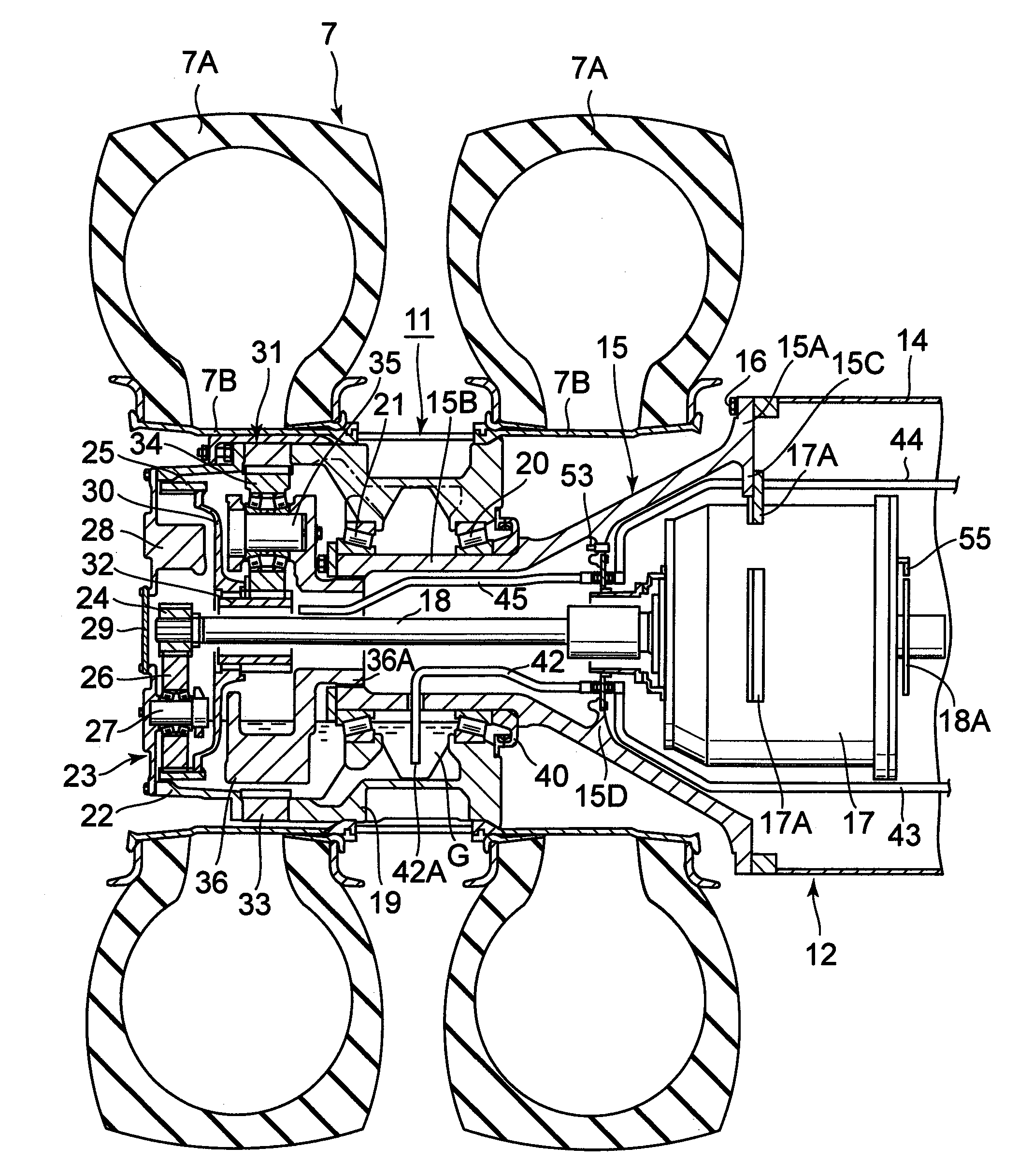
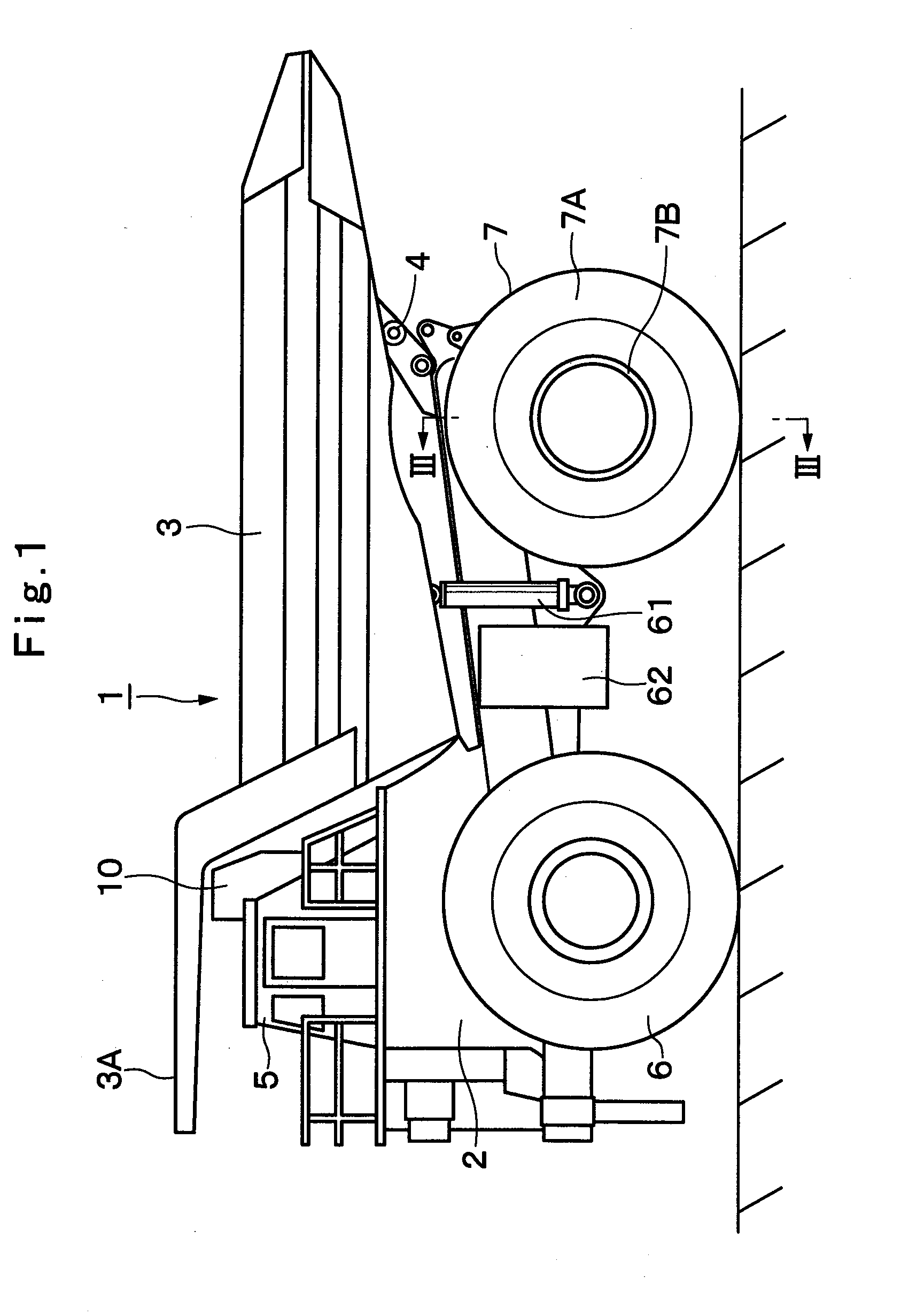
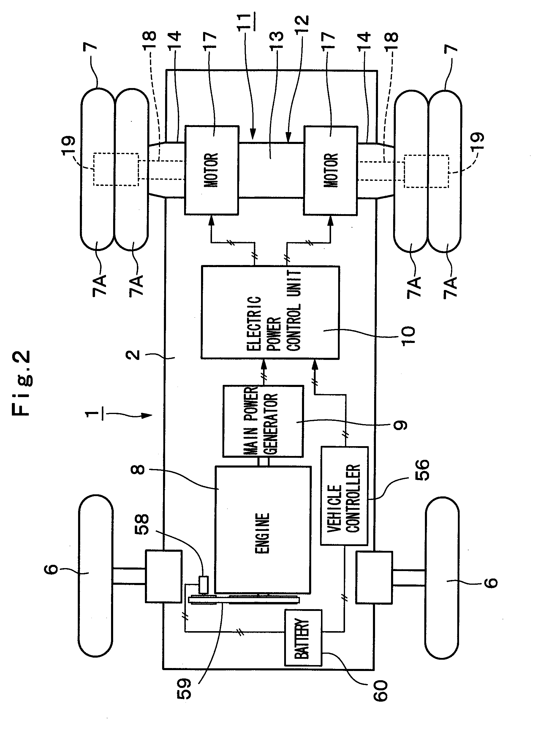
[0085]Shown in FIGS. 1 through 8 is the present invention, i.e., a traveling drive unit for a working vehicle.

[0086]In the drawings, indicated at 1 is a dump truck adopted in the first embodiment as a typical working vehicle. As shown in FIG. 1, the dump truck 1 is built with a sturdy frame structure, and largely constituted by an automotive vehicle body 2 with front and rear wheels 6 and 7, and a vessel 3 which is liftably mounted on the vehicle body 2 as a load-carrying platform.

[0087]Further, the vessel 3 is formed as a large-size container whose overall length reaches as much as 10 to 13 meters to load a large volume of heavy load such as crushed stones or other similar objects, and its rear side bottom portion is liftably (tiltably) coupled to a rear end side of the vehicle body 2 by using a pin coupling portion 4 and the like. Further, protector 3A is projected forward from a front top of the vessel 3 in such a way as to cover a cabin 5 from upper side, which will be described...

second embodiment

[0170]This second embodiment has a feature in that the operation of the lubricant circulation pump 46 is turned on and off by way of an on-off control of the pump drive motor 47 in relation with the temperature T of lubricant oil G, vehicle speed V and output pressure P of the lubricant circulation pump 46.

[0171]Namely, in a lubricant oil supply control routine of FIG. 9, Steps 21 to 29 are executed to carry out the same processing as in Steps 1 to 9 in the first embodiment (FIG. 8). In next Step 30, an output pressure P of the lubricant circulation pump 46 is read in from a pressure sensor 52 (see FIGS. 4 and 7) to judge whether or not the output pressure P is higher than a predetermined reference pressure P1 in Step 31.

[0172]In this instance, the reference pressure P1 is a criterial value to be used in making a judgment as to whether or not the lubricant circulation pump 46 is put in a dry idling operation, that is, disabled to suck in lubricant oil G due to decrease of lubricant ...

third embodiment

[0181]In short, the third embodiment has features in that, by the use of an indicator 57 of FIG. 7, for example, a warning information is given to an operator in the cabin 5 when the temperature T of lubricant oil G has risen for example, in excess of a warning temperature T2 of 90° C. to 100° C. (T2>T1), warning the operator that the temperature T of lubricant oil G is at a high level.

[0182]In this instance, the warning temperature T2 means a temperature value (e.g., 90° C. to 100° C.) which is far higher than the afore-mentioned reference temperature T1 (e.g., 40° C. to 60° C.) in the first embodiment, i.e., for judging an abnormality in the lubricant oil circulation device 41.

[0183]Namely, in the case of the lubricant oil supply control routine of FIG. 10, Steps 41 and 42 are executed to carry out the same processing as in Steps 1 and 2 of the control routine in the first embodiment (see FIG. 8). Then, in next Step 43, a judgment is made as to whether or not the temperature T of ...


PUM


Abstract

A lubricant circulation pump (46) which is driven by an electric motor (47) is provided in the course of a circulation path (41A, 41B) for circulating lubricant oil to a wheel mounting case (19) which is rotated together with a rear wheel (7). Turning on and off the lubricant circulation pump is controlled according to rotational speed of the rear wheel. When lubricant oil in the wheel mounting case sticks on inner peripheral surfaces thereof under the influence of centrifugal force as a result of the increased vehicle speed, the electric motor is turned off to suspend operation of the lubricant circulation pump. Consequently, the lubricant circulation pump does not suck lubricant oil in the wheel mounting case through an inlet opening (42A) of an intake pipe (42), thereby preventing the lubricant circulation pump from being put in a dry idling operation.

Description

TECHNICAL FIELD[0001]This invention relates to a traveling drive unit for working vehicle such as a transportation vehicle and dump truck which is suitably used in transporting crushed stones excavated from a mine or the like, and more particularly to a traveling drive unit for working vehicle, incorporating a reduction gear mechanism to increase the driving torque at the time of traveling.BACKGROUND ART[0002]Generally, large-size transportation vehicles, called dump trucks, have a liftable vessel (a loading platform) on a frame of a vehicle body, and carry heavy objects to be transported like crushed stones in a state in which the objects to be transported are loaded in a large quantity on the vessel.[0003]In this regard, for example, a traveling drive unit which is adapted to drive a drive wheel of a dump truck is provided with a tubular axle housing which is mounted on a vehicle body, a drive source such as an electric motor or a hydraulic motor which is provided in the axle hous...

Claims


Application Information

Patent Timeline
Patent Type & Authority Applications(United States)
IPC IPC(8): F16H57/04F16H1/28F16H57/02
CPCB60B11/06Y02T10/6217B60B27/04B60B35/163B60K1/02B60K6/46B60K7/0007B60K17/046B60K2007/0038B60K2007/0092B60L2240/445B60W10/30B60W20/00B60W2510/0676B60W2520/10B60Y2200/14F16H57/0434B60B25/04Y02T10/62B60W2050/143B60W30/192B60W10/08
Inventor MURAHASHI, TAKAYOSHI
Owner NIHON KENKI CO LTD
Why Eureka
Try Eureka