
Rechargeable battery protection integrated circuit device, rechargeable battery protection module using the rechargeable battery protection integrated circuit device, and battery pack

a rechargeable battery and integrated circuit technology, applied in the direction of safety/protection circuits, secondary cells servicing/maintenance, electrochemical generators, etc., can solve the problems of both charge and discharge, the protection function of the rechargeable battery cannot be performed, and the inability to charge and discharg

Active Publication Date: 2010-06-10
MITSUMI ELECTRIC CO LTD
View PDF3 Cites 32 Cited by
  • Summary
  • Abstract
  • Description
  • Claims
  • Application Information

AI Technical Summary

Benefits of technology

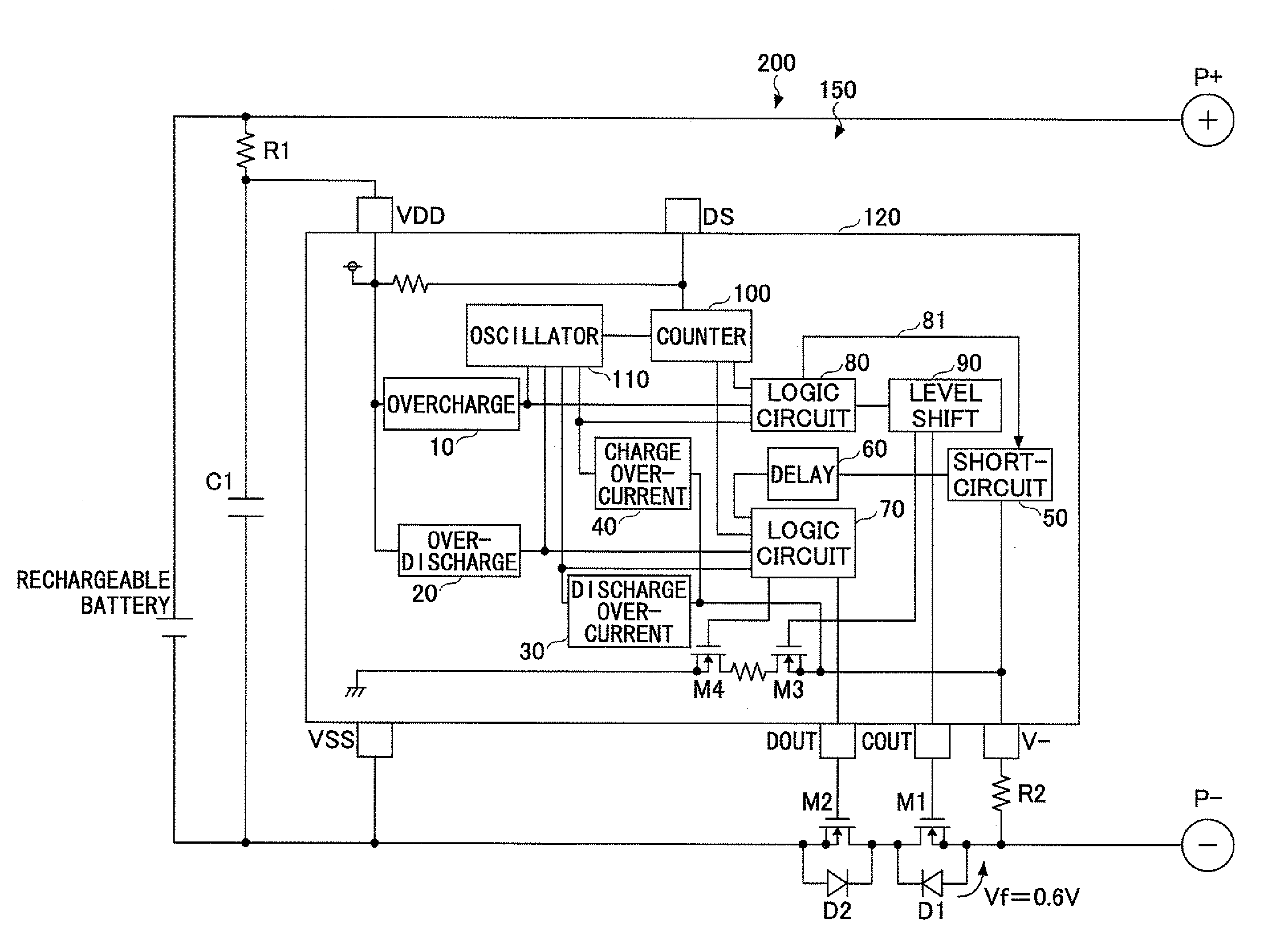
[0018]Accordingly, embodiments of the present invention may provide a novel and useful rechargeable battery protection integrated circuit device, a rechargeable battery protection module using the rechargeable battery protection integrated circuit device, and a battery pack solving one or more of the problems discussed above.
[0019]More specifically, the embodiments of the present invention may provide a rechargeable battery protection integrated circuit device whereby a short circuit state can be properly detected even during an overcharge time so that a rechargeable battery can be always and securely protected regardless of its being a normal time or the overcharge time, a rechargeable battery protection module using the rechargeable battery protection integrated circuit device, and a battery pack.
[0023]According to the embodiments of the present invention, it is possible to detect the short circuit state and protect the rechargeable battery from the short circuit state with high reliability even at the overcharge time.

Problems solved by technology

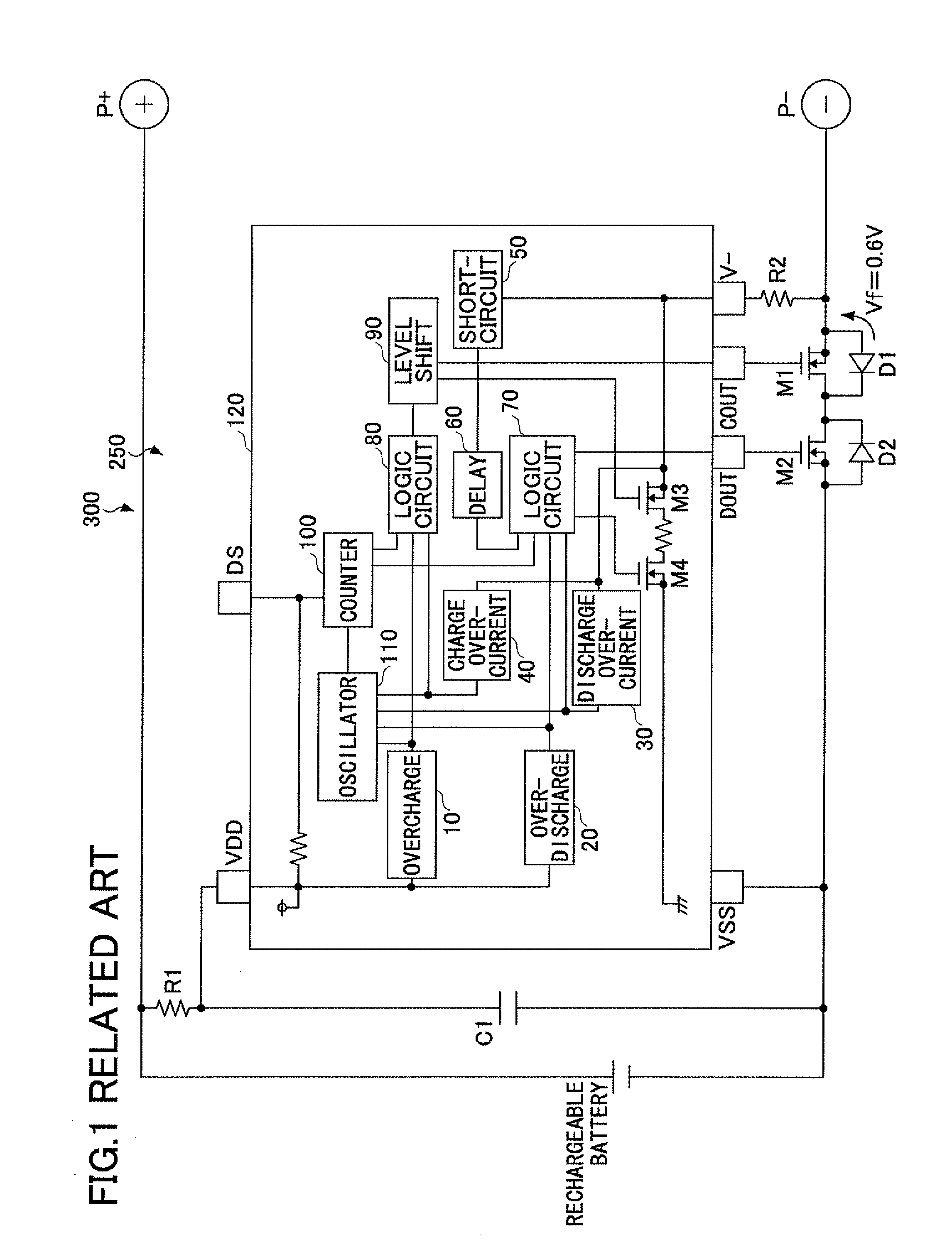
In the meantime, the structure of the related art device shown in FIG. 1 has the following problems.
In other words, in this case, if the discharge control MOS transistor M2 is turned off when the charge control MOS transistor M1 is turned off due to detection of an overcharge, both charge and discharge cannot be performed.
As a result of this, regardless of the overcharge state, the discharge control MOS transistor M2 is turned off, so that both charge and discharge cannot be performed.
Hence, there may be a serious problem with the protection function of the rechargeable battery.
In other words, if the short circuit detection threshold value is too high, the range where the short circuit protection works at the normal time may become narrow.
For example, when the short circuit detection threshold value is 1.0 V higher than 0.6 V, in a case where the on-resistance of the charge control MOS transistor M1 is 50 mΩ, the short circuit protection is performed at the short circuit electric current equal to or greater than 20 A. However, this electric current is too large and it is necessary to perform the short circuit protection when smaller short circuit electric currents flow.
Accordingly, in a case where the electric current limitation by which the short circuit protection is operated is too large, the protection may not be provided when the protection is required.
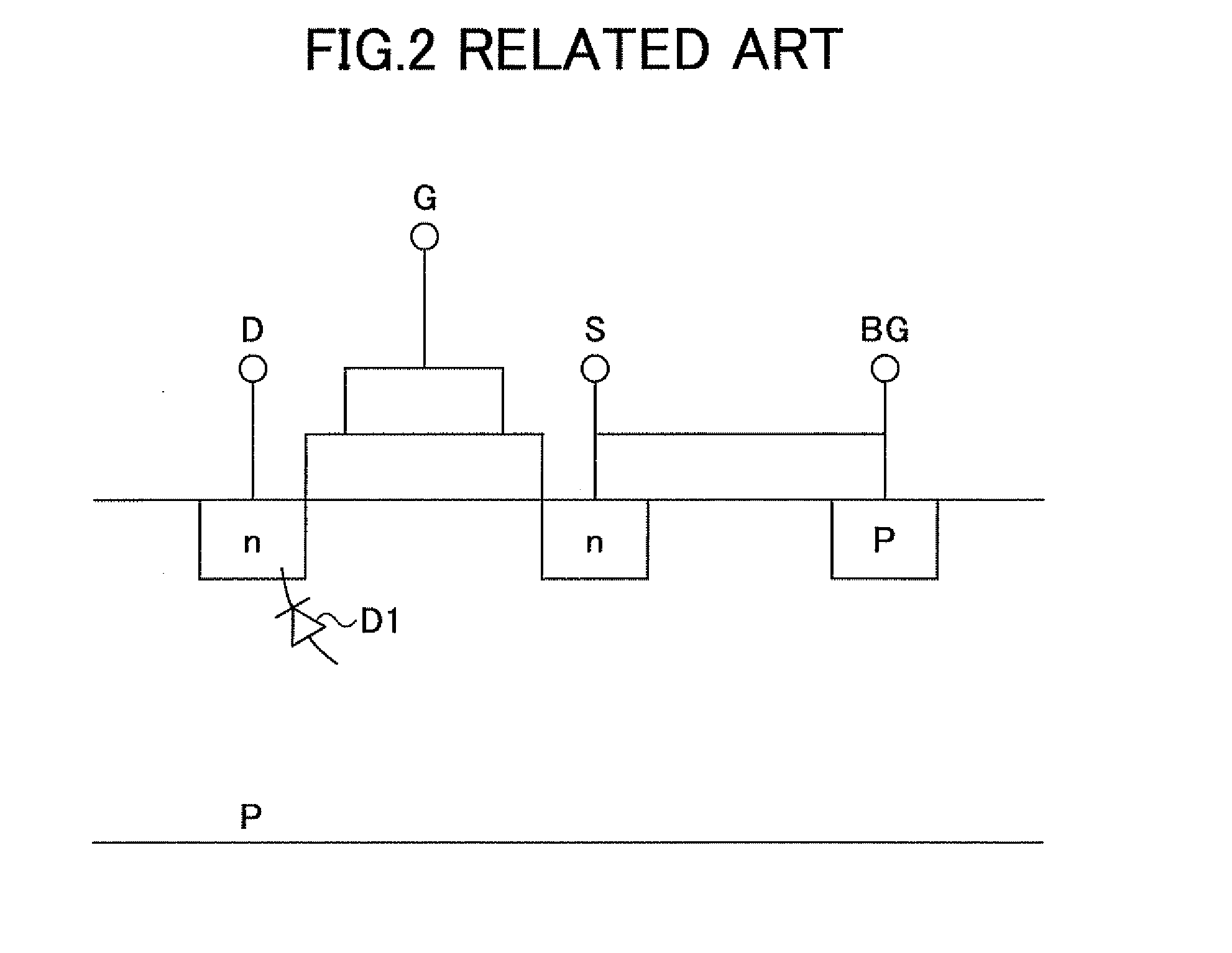
Accordingly, if the short circuit detection voltage of the rechargeable battery protection module 250 is set to be greater than the voltage increase Vf by the body diode D1 of the charge control MOS transistor M1, it may be difficult to meet the demands of the small size and low consumption electric current device.
Therefore, the problems of the short circuit detection at the time of overcharging being the same as those in the related art may remain.

Method used


Image

  • Rechargeable battery protection integrated circuit device, rechargeable battery protection module using the rechargeable battery protection integrated circuit device, and battery pack
  • Rechargeable battery protection integrated circuit device, rechargeable battery protection module using the rechargeable battery protection integrated circuit device, and battery pack
  • Rechargeable battery protection integrated circuit device, rechargeable battery protection module using the rechargeable battery protection integrated circuit device, and battery pack

Examples


second embodiment

[0062]FIG. 7 is a circuit diagram showing an example of a structure of a short circuit detecting circuit 50a of a rechargeable battery protection integrated circuit device 120a of a second embodiment of the present invention. A whole structure of a rechargeable battery protection semiconductor integrated circuit device 120a, a battery protection module, and a battery pack of the second embodiment is substantially the same as that of the first embodiment shown in FIG. 1, and therefore explanation thereof is omitted. In the rechargeable battery protection integrated circuit device 120a of the second embodiment of the present invention, only a structure of a short circuit detecting voltage change part 57a of the short circuit detecting circuit 50a is different from the rechargeable battery protection integrated circuit device 120 and the rechargeable battery protection module 150 of the first embodiment of the present invention.

[0063]As shown in FIG. 7, the short circuit detecting circ...

third embodiment

[0067]FIG. 8 is a circuit diagram showing an example of a structure of a short circuit detecting circuit 50b of a rechargeable battery protection integrated circuit device 120b of a third embodiment of the present invention. The rechargeable battery protection integrated circuit device 120b is different from the rechargeable battery protection integrated circuit devices 120 and 120a of the first and second embodiments in that an electric current source Is and an inverter INV, instead of the voltage dividing circuits 55 and 55a, are provided in the short circuit detecting circuit 50b. A whole structure of a rechargeable battery protection semiconductor integrated circuit device 120b, a battery protection module 150, and a battery pack 200 of the third embodiment is substantially the same as that of the first embodiment shown in FIG. 1, and therefore explanation thereof is omitted.

[0068]As shown in FIG. 8, the short circuit detecting circuit 50b of the third embodiment includes a shor...


PUM


Abstract

A rechargeable battery protection integrated circuit device, includes a short circuit detecting circuit configured to convert a discharge electric current of a rechargeable battery to a voltage value and detect a short circuit state of the rechargeable battery when the converted voltage value is equal to or greater than a designated short circuit detecting voltage; a discharge control terminal configured to output a control signal when the short circuit state is detected by the short circuit detecting circuit, the control signal being configured to stop a discharge of the rechargeable battery; and an overcharge detecting circuit configured to detect an overcharge of the rechargeable battery, wherein the short circuit detecting circuit includes a short circuit detecting voltage change part, the short circuit detecting voltage change part being configured to change the short circuit detecting voltage when the overcharge is detected by the overcharge detecting circuit.

Description

CROSS-REFERENCE TO RELATED APPLICATIONS[0001]This patent application is based upon and claims the benefit of priority of Japanese Patent Application No. 2008-310105 filed on Dec. 4, 2008 the entire contents of which are incorporated herein by reference.BACKGROUND OF THE INVENTION[0002]1. Field of the Invention[0003]The present invention generally relates to rechargeable battery protection integrated circuit devices, rechargeable battery protection modules using the rechargeable battery protection integrated circuit devices, and battery packs. More specifically, the present invention relates to a rechargeable battery protection integrated circuit device including a short circuit detecting circuit, the short circuit detecting circuit being configured to convert a discharge current of a rechargeable battery to a voltage value and detect a short circuit state of the rechargeable battery when the voltage value is equal to or greater than a short circuit detecting voltage, a rechargeable ...

Claims


Application Information

Patent Timeline
Patent Type & Authority Applications(United States)
IPC IPC(8): H02J7/00
CPCH01M10/0525H01M10/48H02J2007/004H02J2007/0037H02J2007/0039H02J7/0031H02J7/00302H02J7/00304H02J7/00306Y02E60/10H01M10/00H01M10/44H02H7/18H02J7/00
Inventor TAKEDA, TAKASHI
Owner MITSUMI ELECTRIC CO LTD
Learn More