Calibrating device for calibration and image measurement system comprising calibrating device

a calibration device and image measurement technology, applied in the field of calibration devices for image measurement systems comprising calibration devices, can solve the problems of inability to accurately print or apply color paint to the calibration device, inability to accurately detect the characteristic portion of the image measurement system, and various limitations in the use of paint in some places, so as to achieve stable detection of the characteristic portion, less cost, and easy handling

Active Publication Date: 2010-06-10
FANUC LTD
View PDF7 Cites 21 Cited by
  • Summary
  • Abstract
  • Description
  • Claims
  • Application Information

AI Technical Summary

Benefits of technology

[0011]An object of the present invention is to provide a calibrating device for calibration in an image measurement system which enables stable detection of a characteristic portion of the calibrating device and precisely independent of the illumination conditions, and is less costly and easily handled.

Problems solved by technology

However, it was difficult to accurately print or apply color paint to the calibrating device.
Further, when the characteristic portion is formed by applying colored paint, the surface of the paint may be smooth depending on the forming method, and the characteristic portion reflects the outside light, and thus, the image measurement system cannot stably detect the characteristic portion.
Also, the paint may be altered by temperature or may be melted by an organic solvent, and further, there are various limitations in the use of the paint in some places.
Therefore, when the characteristic portion is formed by paint, such limitations in the use of the paint must be taken into consideration.
However, the above-mentioned conventional methods have the following drawbacks.
In the case of the magnification calibration plate disclosed in Japanese Patent No. 3409931, it is difficult to accurately vapor-deposit deposition materials such as chrome.
Also, in the case of the calibration gauge disclosed in Japanese Patent No. 3477139, it is difficult to accurately draw the line segment on the metal plate with colored ink.
Therefore, there is a problem that depending on illumination conditions, the characteristic portion cannot be distinguished from the surroundings due to the reflected light, and thus, the image measurement system cannot stably detect the characteristic portion.
The calibration apparatus disclosed in Japanese Patent No. 3512092 has a problem that an expensive liquid crystal panel is required, which leads to an increase in production costs.
In the calibrating device disclosed in Japanese Patent No. 3575165, there is a problem that the spherical mark which serves as a characteristic portion must be produced with accuracy, which leads to an increase in the production costs.
In the photogrammetric target disclosed in Japanese Patent No. 3737919, it is difficult to accurately adhere the plurality of reflective sheets.

Method used


Image

  • Calibrating device for calibration and image measurement system comprising calibrating device
  • Calibrating device for calibration and image measurement system comprising calibrating device
  • Calibrating device for calibration and image measurement system comprising calibrating device

Examples


first embodiment

[0039]Hereinafter, a first embodiment of the present invention will be explained with reference to the attached drawings. In the drawings below, the same reference numeral is used for the same member. The scales of these drawings have been appropriately changed for easy understanding.

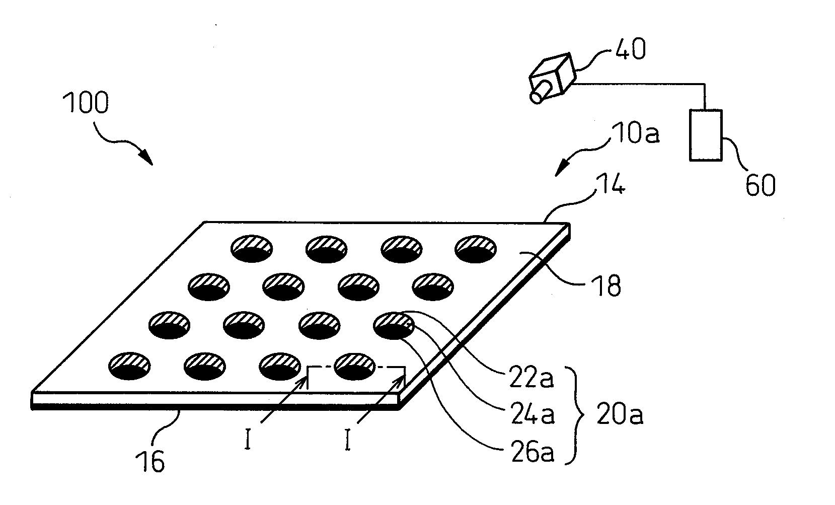
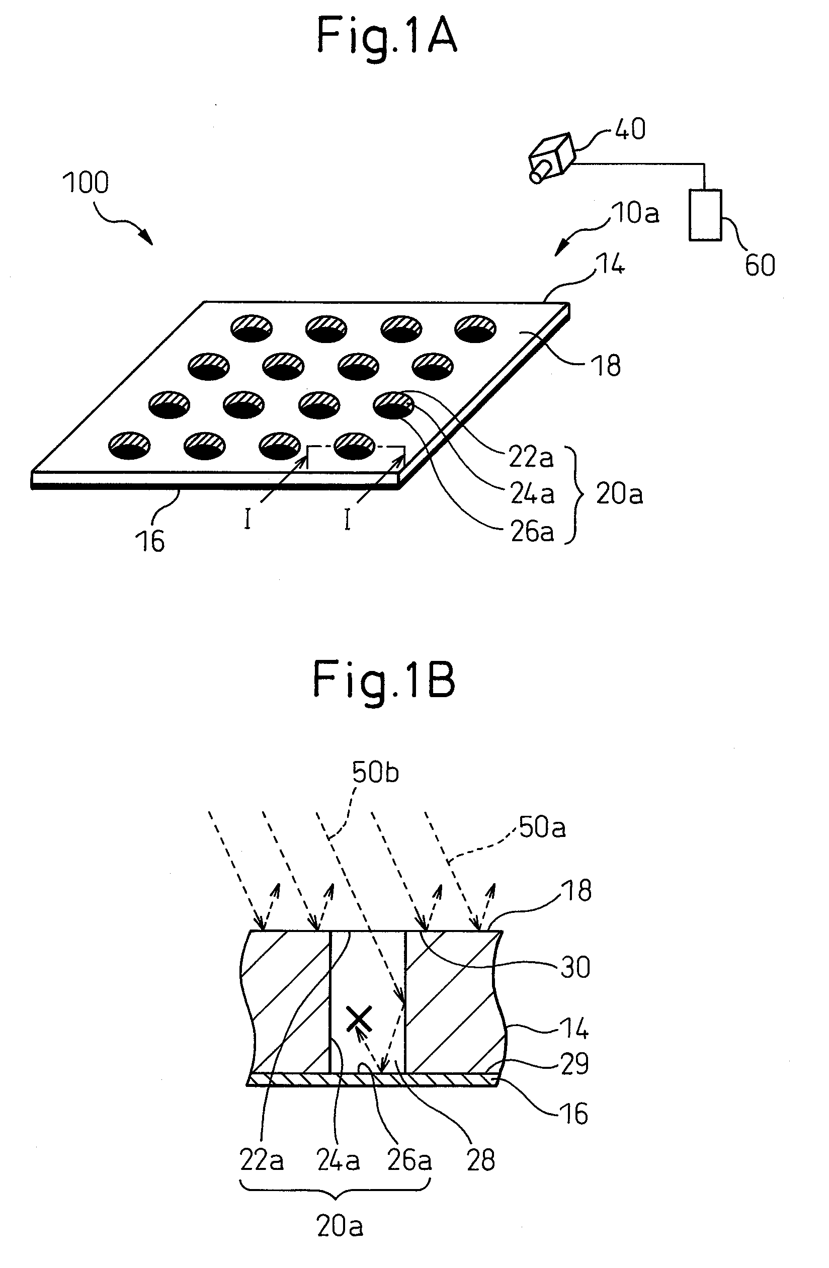
[0040]FIG. 1A is a perspective view showing an image measurement system 100 comprising a calibrating device 10a of the first embodiment and a camera 40 for imaging the calibrating device 10a. FIG. 1B is a cross sectional view along the line I-I of FIG. 1A showing a characteristic portion 20a of the calibrating device 10a.

[0041]First, with reference to FIG. 1A, the image measurement system 100 using the camera 40 will be explained. The image measurement system 100 is configured by the calibrating device 10a provided with the characteristic portion 20a in the form of a recess, the camera 40 for imaging the calibrating device 10a, and an image processing section 60 connected to the camera 40 to process th...

second embodiment

[0058]FIG. 4A is a perspective view showing an example of the calibrating device according to the second embodiment. FIG. 4B is a perspective view of another example of the calibrating device according to the second embodiment. FIG. 5A is a cross sectional view along the line V-V of FIG. 4A and shows the characteristic portion 20b of the calibrating device 10b shown in FIG. 4A. FIG. 5B is a cross sectional view along the line V-V of FIG. 4A and shows the characteristic portion 21b which is another example of the characteristic portion 20b.

[0059]The second embodiment will be explained using FIG. 4A to FIG. 5B. The calibrating devices 10b and 10c according to the second embodiment are different from the calibrating device 10a according to the first embodiment in terms of the method of forming the recess.

[0060]First, the characteristic portion of the calibrating device according to the second embodiment will be explained. The plate 14 of the calibrating device 10b shown in FIG. 4A is ...

third embodiment

[0066]FIG. 6A is a plan view of the image measurement system 100 showing a positional relationship between a calibrating device 10d according to the third embodiment and the camera 40. FIG. 6B is a cross sectional view along the line VI-VI of FIG. 6A. FIG. 6C is a view showing a part of a measurement image 45d of the calibrating device 10d imaged by the camera 40. The third embodiment will be explained using FIG. 6A to FIG. 6C.

[0067]The calibrating device 10d according to the third embodiment has a feature that the shape and size of the characteristic portion 21d of the calibrating device 10d is set so as to not image the side surface 25d of the characteristic portion 21d when the camera 40 images the characteristic portion 21d, by the angle of the optical axis of the camera 40 predetermined with respect to the characteristic portion 21d for calibration in image measurement system 100. The structure of the characteristic portion 21d is the same as the characteristic portion 21a of t...


PUM


Abstract

A calibrating device for calibration of an image measurement system. The calibrating device includes a main body having an upper surface, and a characteristic portion, which serves as a benchmark for calibration and is in the form of a recess formed in the upper surface of the main body, wherein the characteristic portion includes a side surface extending in a direction crossing the upper surface, and a bottom surface extending in a direction crossing the side surface, the bottom surface has an optical reflectance lower than an optical reflectance of the upper surface in relation to light identical to each other. This can provide a calibrating device for calibration of an image measurement system, which can detect the characteristic portion on the calibrating device stably, precisely and independent of the illumination conditions, which is less costly and can be easily handled.

Description

BACKGROUND OF THE INVENTION[0001]1. Field of the Invention[0002]The present invention relates to a calibrating device for calibration of an image measurement system using a camera. Specifically, the present invention relates to a calibrating device imaged by a camera for calibrating the internal parameters of the camera, mechanical parameters of a robot, etc., and an image measurement system comprising the calibrating device.[0003]2. Description of the Related Art[0004]Conventionally, an image measurement system using a camera is utilized in various industrial field. In such an image measurement system, an object is imaged by a camera, the image is subjected to image processing by an image processing apparatus, etc., and the position, shape, size, and angle of the object are measured. Further, in order to use a camera for measurement, an operator must calibrate (correction) the camera using a calibrating device prior to the measurement. Usually, in an image measurement system, the c...

Claims


Application Information

Patent Timeline
IPC IPC(8): H04N17/00
CPCB25J9/1692G06T7/0018G05B2219/39045G05B2219/37563G06T7/80
Inventor BAN, KAZUNORITAKIZAWA, KATSUTOSHISHEN, GANGWATANABE, KEISUKE
Owner FANUC LTD
Why Eureka
Try Eureka