Image processing device, control program, computer-readable storage medium, electronic apparatus, and image processing device control method

a control program and image processing technology, applied in the direction of image analysis, instruments, computing, etc., can solve the problems of large memory, time-consuming identification of touch positions, and patent literature 1 does not even disclose, so as to improve the robustness of image input to noise and deformation, improve the processing time, and improve the effect of robustness

Inactive Publication Date: 2010-06-10
SHARP KK
View PDF10 Cites 18 Cited by
  • Summary
  • Abstract
  • Description
  • Claims
  • Application Information

AI Technical Summary

Benefits of technology

[0017]The present invention, conceived in view of these conventional problems, has an objective of providing an image processing device, etc. capable of detection of a position in a captured image pointed at with an image capture object with small memory and short processing t

Problems solved by technology

The touch/non-touch detection thus requires information for at least two frames or even more, which in turn disadvantageously requires large memory.
Another problem is that the identification of the touch position is time-consuming because the device is adapted to calculate the center of mass of the edge as the coordinate posi

Method used


Image

  • Image processing device, control program, computer-readable storage medium, electronic apparatus, and image processing device control method
  • Image processing device, control program, computer-readable storage medium, electronic apparatus, and image processing device control method
  • Image processing device, control program, computer-readable storage medium, electronic apparatus, and image processing device control method

Examples


Embodiment Construction

[0096]The following will describe an embodiment of the present invention in reference to FIGS. 1 to 11. The present embodiment employs a liquid crystal display device as an exemplary image display section. The present invention is however also applicable to image display sections that are not liquid crystal display devices.

1. Configuration of Image Processing Device (Electronic Apparatus)

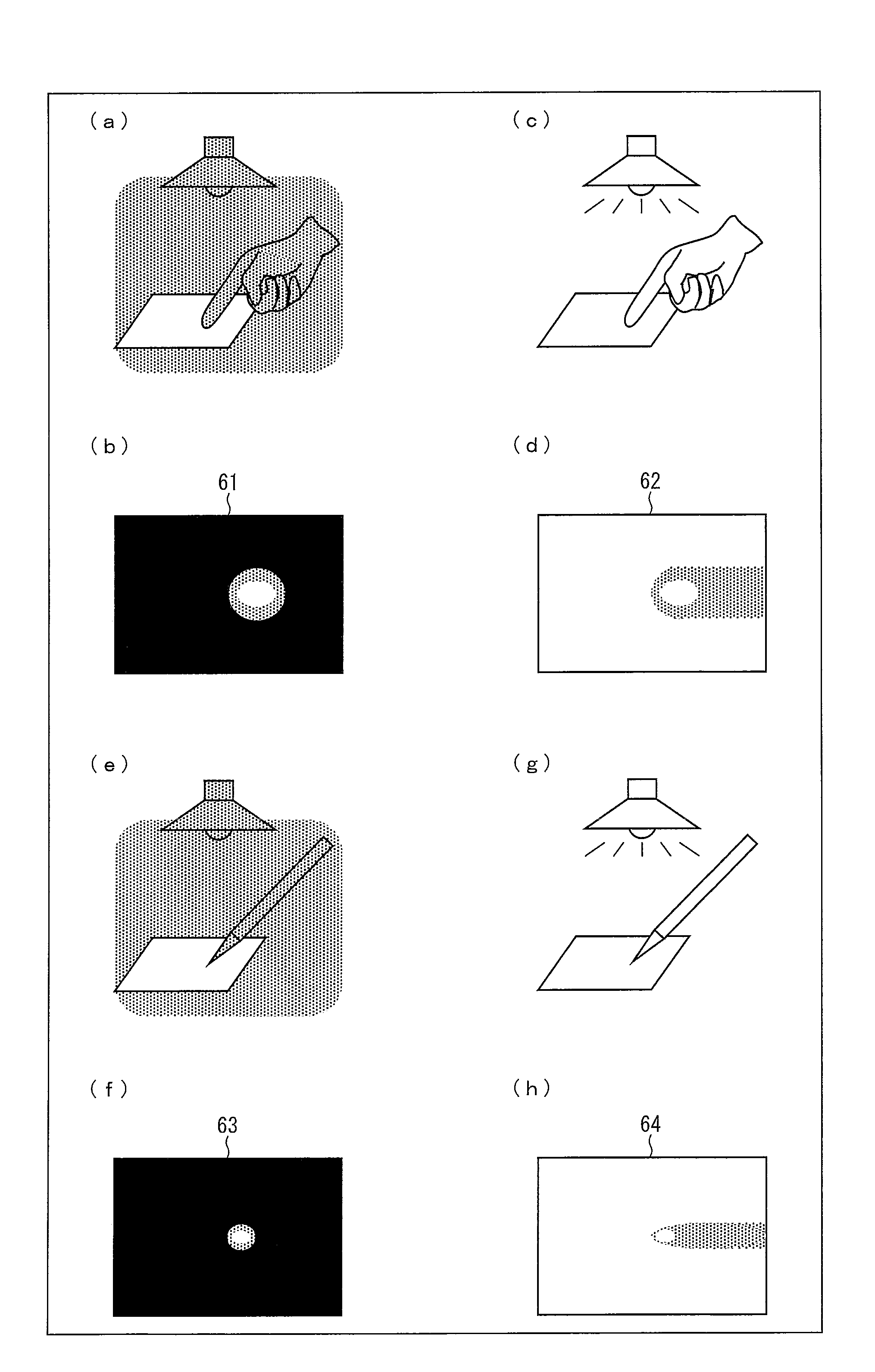
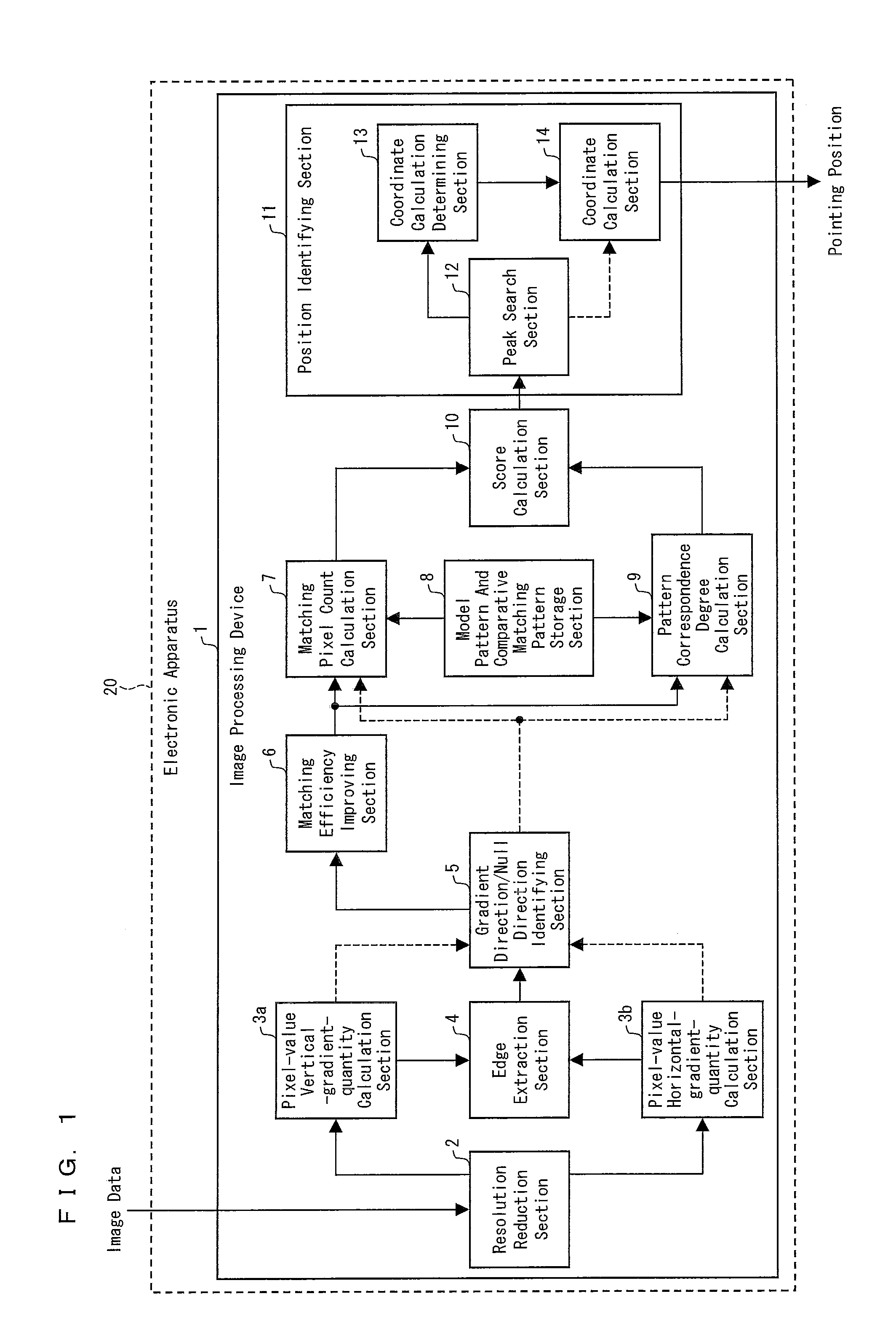
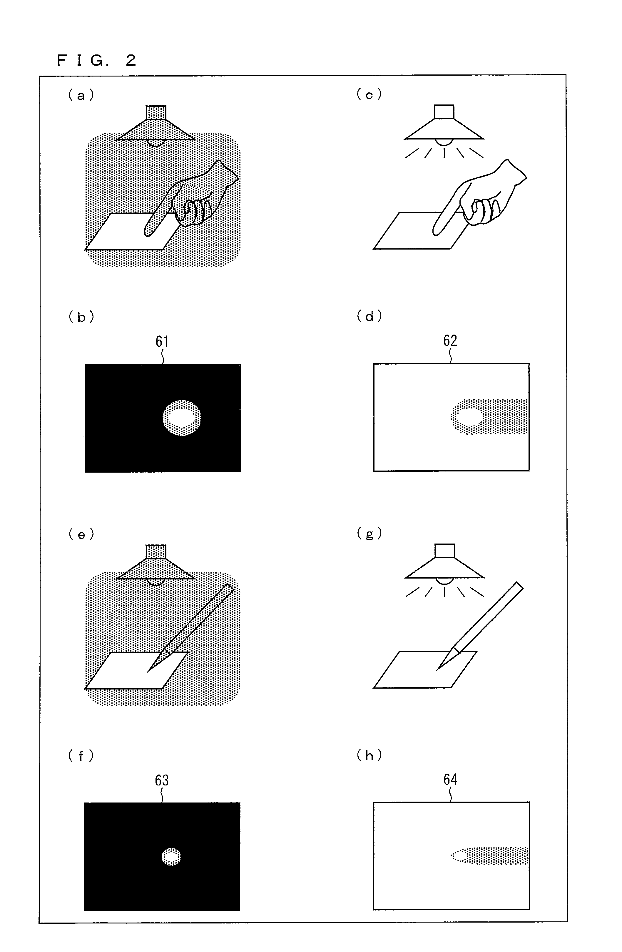
[0097]First, referring to FIGS. 1 and 2(a) to 2(h), the configuration of an image processing device 1 (electronic apparatus 20) which is an embodiment of the present invention and an exemplary captured image will be described. Although the following description will be focused on the image processing device 1 for convenience, the present embodiment is applicable to general electronic apparatus provided that the apparatus is electronic apparatus (electronic apparatus 20) which needs the functions of the image processing device 1 which is an embodiment of the present invention.

[0098]First, an overview...


PUM


Abstract

The invention includes: a pixel-value vertical-gradient-quantity calculation section (3a) and a pixel-value horizontal-gradient-quantity calculation section (3b) for calculating, for each pixel in image data, a vertical-direction gradient quantity (Sy) and a horizontal-direction gradient quantity (Sx) for a pixel value; a gradient direction/null direction identifying section (5) for identifying, for each pixel, either a gradient direction or null direction from the vertical-direction gradient quantity (Sy) and the horizontal-direction gradient quantity (Sx); a score calculation section (10) for calculating an correspondence degree from a number of pixels for which a gradient direction contained in the matching region matches a gradient direction contained in the model pattern and a pattern correspondence degree which is a degree of similarity of a matching pattern between the gradient direction for each pixel in the matching region and the gradient direction for each pixel in the model pattern to a comparative matching pattern; and a position identifying section (11) for identifying the position in the captured image pointed at with the image capture object from a position of a target pixel for which the correspondence degree is a maximum.

Description

TECHNICAL FIELD[0001]The present invention relates to image processing devices having a function of identifying a position in a captured image pointed at with an image capture object by using image data for the captured image.BACKGROUND ART[0002]It is well known that image display devices built around various devices, such as mobile phones or PDAs (Personal Digital Assistants), and equipped with a liquid crystal display device as an image display section (hereinafter, “liquid crystal display devices”) are in popular use. Especially, the PDA traditionally contains touch sensors to enable a touch input whereby the user can input information by directly touching the liquid crystal display device with, for example, a finger. It is expected that broad ranges of mobile phones and like devices will also adopt a liquid crystal display device which come with touch sensors.[0003]Patent Literature 1 discloses technology as an example of the liquid crystal display device incorporating touch sen...

Claims


Application Information

Patent Timeline
IPC IPC(8): G06K9/62G06F3/041
CPCG06F3/042G06T7/0046G06K9/00375G06T7/75G06V40/107
Inventor YAHATA, YOICHIRO
Owner SHARP KK
Why Eureka
Try Eureka