Apparatus for Transferring Optical Data in Optical Switching System Using Time Synchronization

Inactive Publication Date: 2010-06-10
ICU RES & INDAL COOPERATION GROUP
View PDF5 Cites 17 Cited by
  • Summary
  • Abstract
  • Description
  • Claims
  • Application Information

AI Technical Summary

Benefits of technology

[0024]According to the apparatus and method for transferring optical data in an optical switching system using time synchronization, the time synchronization is performed on all optical data before the optical data are input to a switch, and the optical data are input with a uniform size at regular intervals. Thus, a data blocking rate can be reduced to be lower than that of a conventional optical switching system using an asynchronous electric buffer without a synchronization process, and system cost is reduce

Problems solved by technology

However, only an extremely small part of the technology has been developed into solutions for a high-speed (peta-bits/second) broadband system suitable for real application requirements regarding performance, cost, power consumption, and so on.
Here, most active technology enables complex optical signal processing using a semiconductor optical amplifier (SOA) and a wavelength converter, but this requires complex control, consumes much power, and needs

Method used


Image

  • Apparatus for Transferring Optical Data in Optical Switching System Using Time Synchronization
  • Apparatus for Transferring Optical Data in Optical Switching System Using Time Synchronization
  • Apparatus for Transferring Optical Data in Optical Switching System Using Time Synchronization

Examples


Embodiment Construction

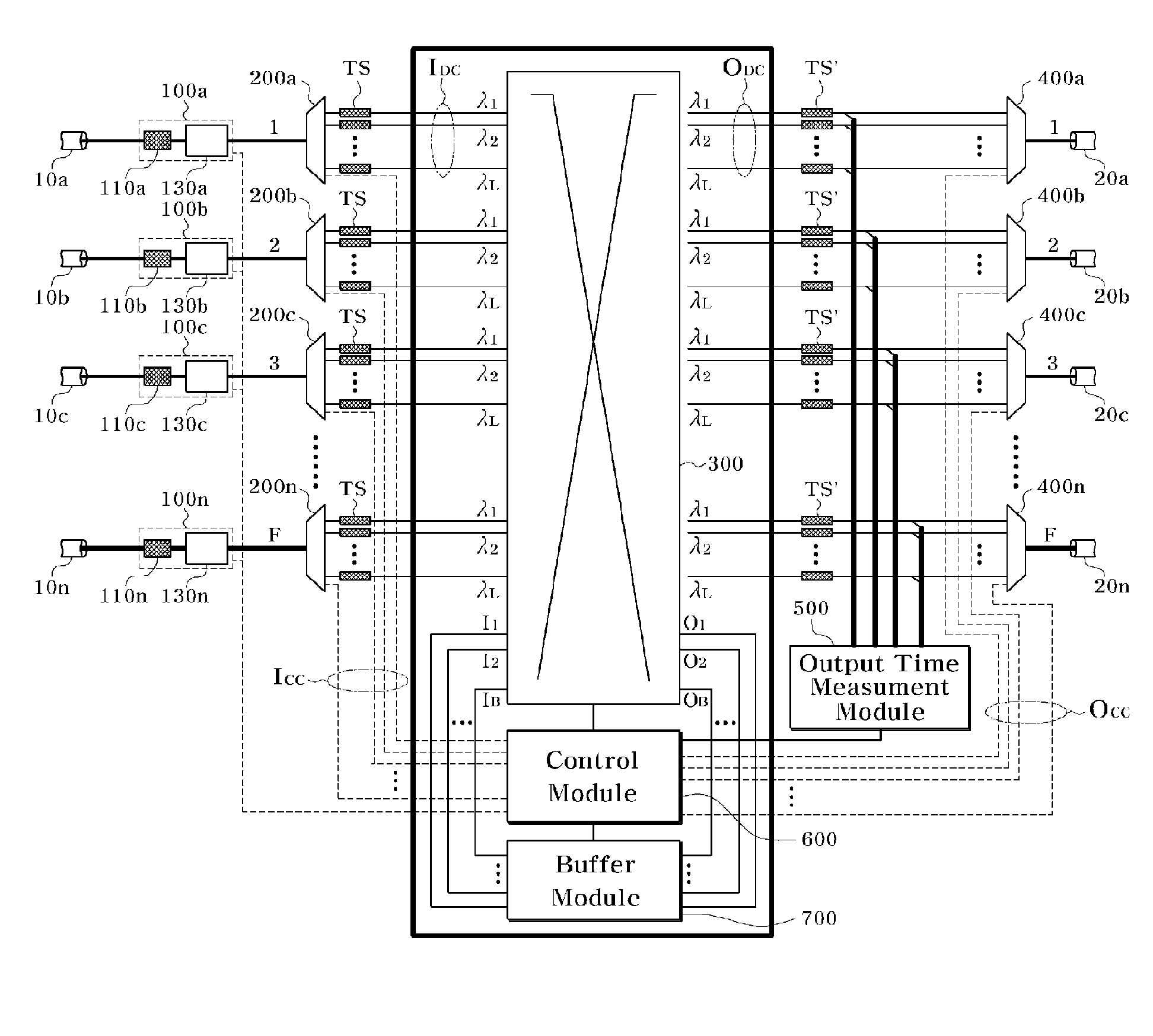
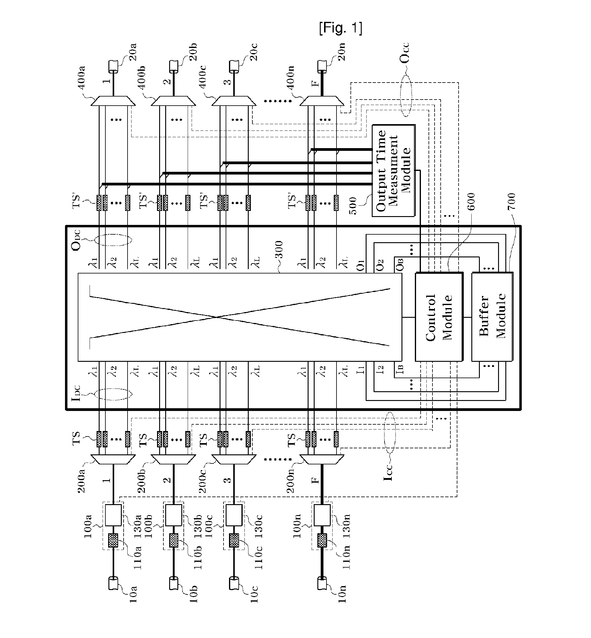
[0034]An apparatus for transferring optical data according to an exemplary embodiment of the present invention can be used in all the optical switching systems, e.g., an optical packet switching system and an optical burst switching system.

[0035]First of all, terminology generally used in this specification including the title of the present invention, detailed description, claims, etc. will be defined in brief.

[0036]The terminology “optical data” indicates all data transferred from each node in an optical switching system. Particularly, in an optical packet switching system, it means an optical packet including a header packet and a data packet and, in an optical burst switching system, an optical burst having a control packet and a data burst.

[0037]The terminology “transfer information” indicates every kind of information for transferring the above-described optical data to a desired destination node. Particularly, in an optical packet switching system, the terminology includes he...


PUM


Abstract

Provided is an apparatus for transferring optical data in an optical switching system using time synchronization. The apparatus performs time synchronization on optical data to input the optical data at regular intervals through fiber delay line for time synchronization respectively disposed on input ports. Therefore, the apparatus can efficiently reduce a data blocking rate in comparison with a conventional optical switching system using an asynchronous electric buffer without a synchronous process, and achieve the same performance as conventional asynchronous technology despite using fewer wavelength converters and buffers, thus reducing system cost. In addition, using dynamic time synchronization modules, the apparatus performs time synchronization for minute time variation due to an environment such as temperature.

Description

TECHNICAL FIELD [0001]The present invention relates to an apparatus for transferring optical data in an optical switching system. More particularly, the present invention relates to an apparatus for transferring optical data in an optical switching system using time synchronization, capable of efficiently performing optical data transfer using a few shared buffers by decreasing the probability of contention between optical data when the input optical data are time-synchronized for passive switching.BACKGROUND ART [0002]Optical burst switching (OBS) and optical packet switching (OPS) are a very advanced research area in the optical network field. However, only an extremely small part of the technology has been developed into solutions for a high-speed (peta-bits / second) broadband system suitable for real application requirements regarding performance, cost, power consumption, and so on.[0003]The optical packet or optical burst switching is mainly classified into two hardware function...

Claims


Application Information

Patent Timeline
IPC IPC(8): H04B10/08
CPCH04Q11/0005H04Q11/0066H04Q2011/0045H04Q2011/0035H04Q2011/0039H04Q2011/0016G02B6/293G02B6/35
Inventor RHEE, JUNE KOOKIM, JI HWANCHOI, JUNG YULKANG, MIN HO
Owner ICU RES & INDAL COOPERATION GROUP
Why Eureka
Try Eureka