Composite member fixing structure

Inactive Publication Date: 2010-06-10
TOYOTA BOSHOKU KK +1
View PDF12 Cites 26 Cited by
  • Summary
  • Abstract
  • Description
  • Claims
  • Application Information

AI Technical Summary

Benefits of technology

[0009]Accordingly, it is an objective of the present invention to provide a composite member fixing

Problems solved by technology

Therefore, when molding the composite member in a mold, the flowing pressure of synthetic resin injected into the mold is likely to cause the adhesive to leak from the groove.
In such cases, it is difficult to obtain a desired sealing.
In addition, adhesive that leaks out from the groove reaches the outer surface of the cylinder head cover, and contaminates the outer surface.
In other cases, adhesive that leaks at the molding contamin

Method used


Image

  • Composite member fixing structure
  • Composite member fixing structure
  • Composite member fixing structure

Examples


first embodiment

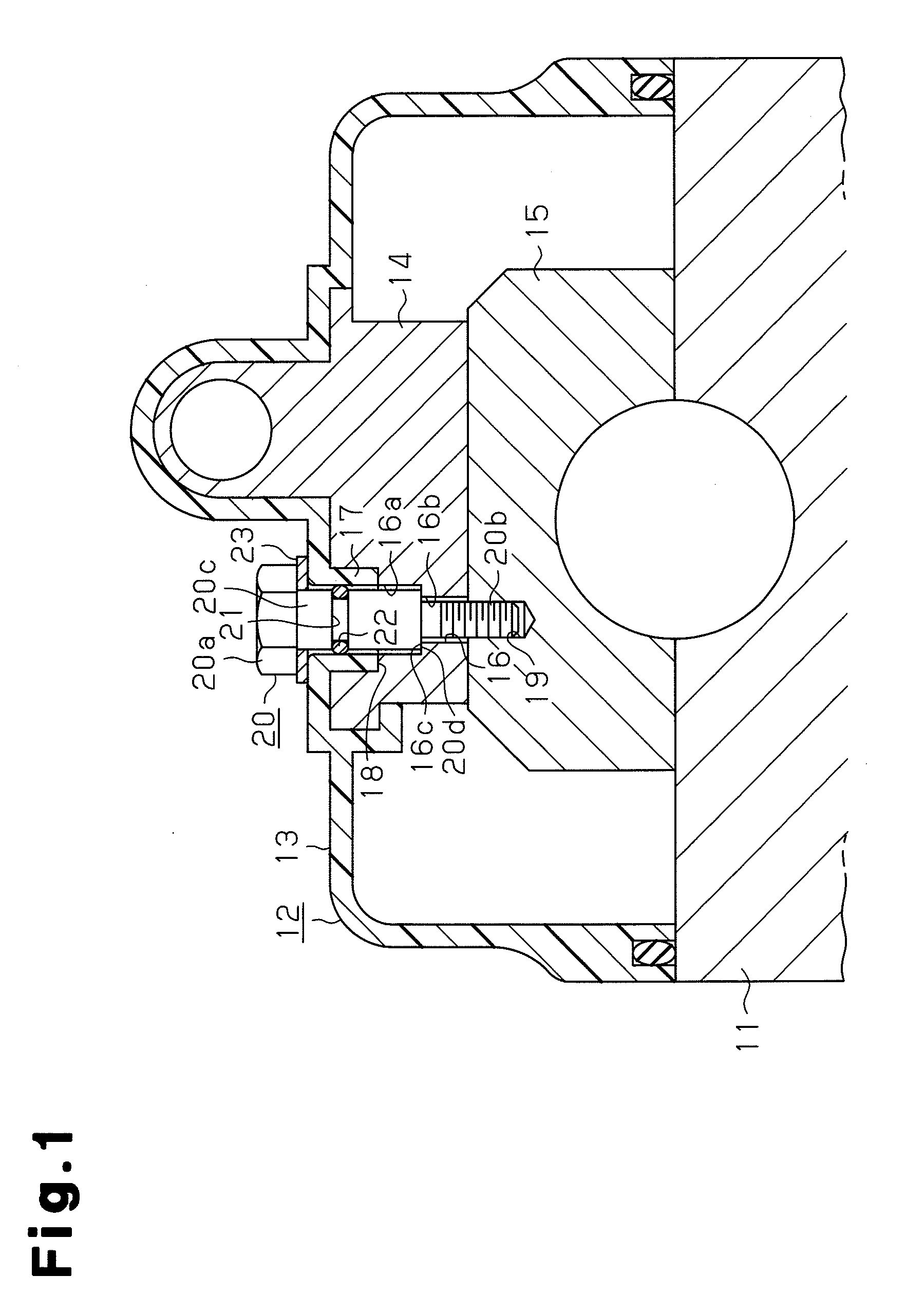
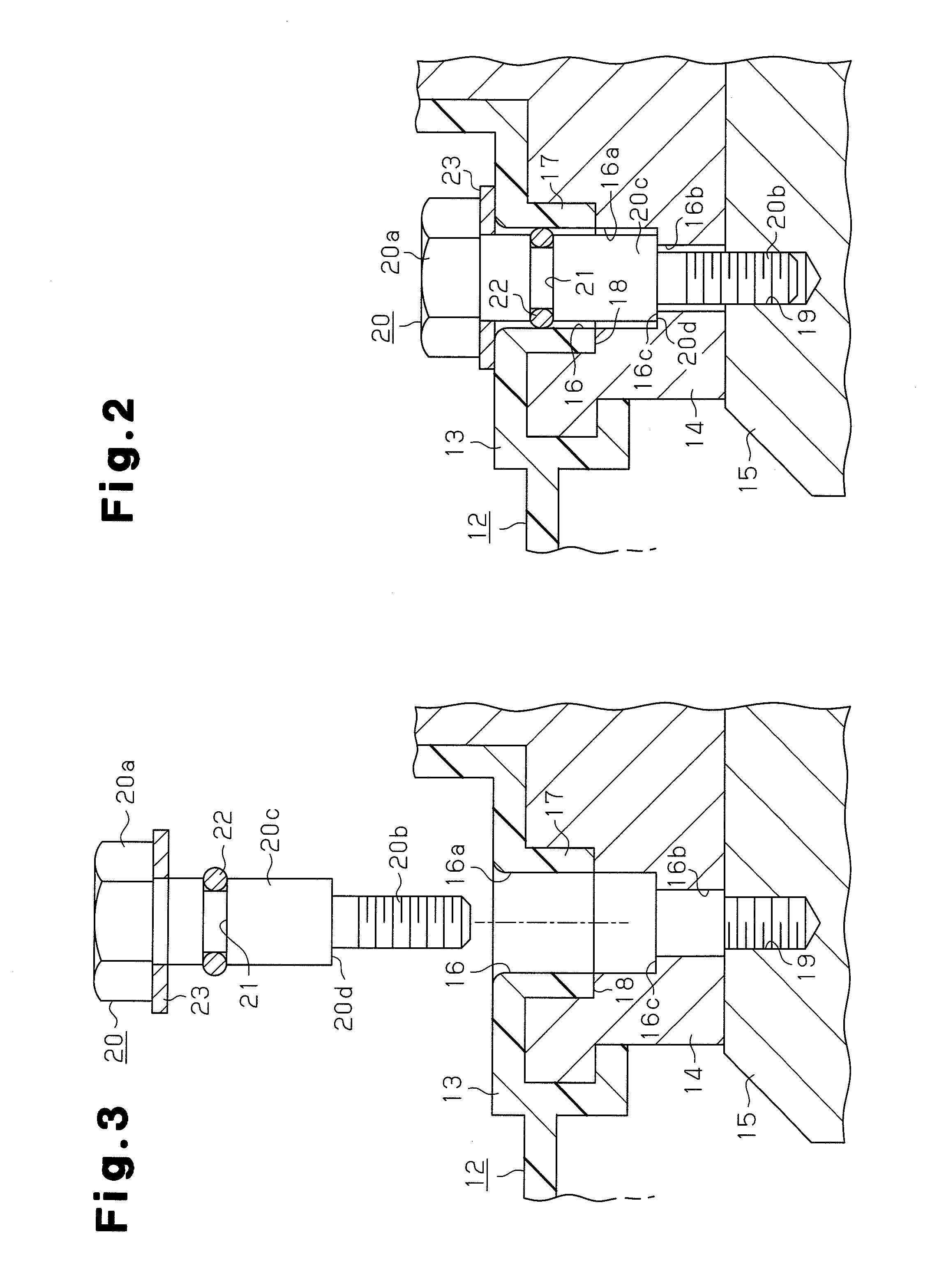
[0018]A composite member fixing structure according to a first embodiment will now be described with reference to FIGS. 1 to 3.

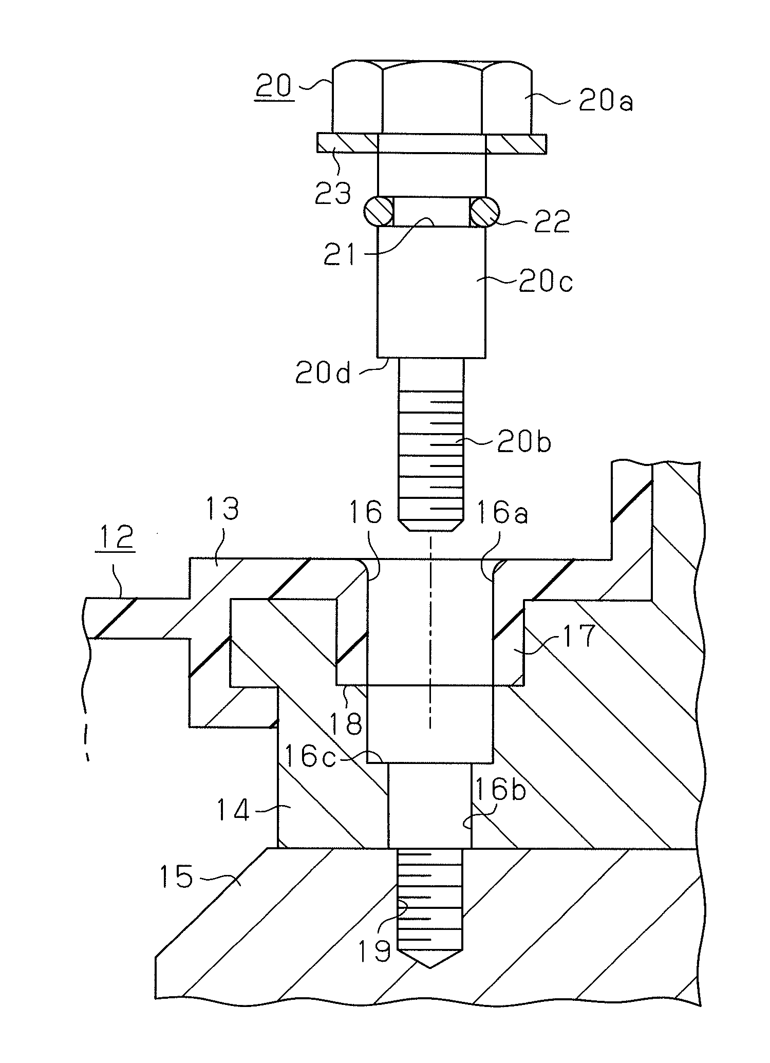
[0019]As shown in FIG. 1, in a vehicle engine, a composite member 12 is fixed onto a cylinder head 11, which is made of metal such as an aluminum alloy, using a plurality of bolts (not shown). The composite member 12 has a composite structure in which a housing 14 of an oil control valve (hereinafter, simply referred to as OCV housing), which is a metal member, is integrated with a cylinder head cover 13, which is a resin member, by insert molding. The cylinder head cover 13 is made of synthetic resin such as a polyamide resin. The OCV housing 14 is made of metal such as an aluminum alloy. In the composite member 12, a cam cap 15, which is a coupled member made of metal such as an aluminum alloy, is fixed to the upper surface of the cylinder head 11.

[0020]A vertically extending bolt insertion hole 16 is formed through the cylinder head cover 13 and the OCV h...

second embodiment

[0033]Next, a second embodiment of the present invention will be described with reference to FIG. 4. The differences from the first embodiment will mainly be discussed below.

[0034]In the second embodiment, an annular sealing member 31 is located between the head 20a of the bolt 20 and the upper surface of the cylinder head cover 13. Therefore, in addition to the sealing function, the sealing member 31 has a function as a washer.

[0035]The second embodiment thus has the following advantage.

[0036](6) Since the sealing member 31 also functions as a washer, there is no need to provide a washer. As a result, the number of the components required for the fixing structure is reduced, which simplifies the fixing structure.

(Modifications)

[0037]It should be noted that the embodiments shown above may be modified as follows.

[0038]In the second embodiment, a circumferential groove 21 may be formed in the shank 20c of the bolt 20, and a sealing member 22 may be fitted in the circumferential groove...


PUM


Abstract

A composite member 12, which is formed by integrating an OCV housing 14 and a cylinder head cover 13, is fixed to a cam cap 15 by a bolt 20. The bolt 20 is passed through a bolt insertion hole 16 of the composite member 12 and fastened to the cam cap 15. A step portion 20d is formed in a shank 20c between a head 20a and a threaded rod 20b of the bolt 20. A circumferential groove 21 is formed in the shank 20c between the step portion 20d and the head 20a of the bolt 20. The circumferential groove 21 extends along the outer circumferential surface of the shank 20c. An annular sealing member 22 is fitted in the groove 21. The threaded rod 20b of the bolt 20 is then screwed into the internal thread 19 of the cam cap 15, which is a coupled member. At this time, the step portion 20d of the bolt 20 contacts a contacting portion 16c in the bolt insertion hole 16 of the OCV housing 14. Also, the sealing member 22 contacts the inner circumferential surface of the bolt insertion hole 16 of the cylinder head cover 13.

Description

BACKGROUND OF THE INVENTION[0001]The present invention relates to a composite member fixing structure, and more particularly, to a fixing structure, for example, in a vehicle engine, which structure fixes a composite member, which includes a synthetic resin cylinder head cover and a metal housing of an oil control valve, to a coupled member such as a cam cap arranged on a cylinder head.[0002]Conventionally, for example, Japanese Laid-Open Patent Publication No. 2007-107479 (first prior art) and Japanese Laid-Open Patent Publication No. 2007-100657 (second prior art) disclose this type of composite member fixing structure.[0003]According to the fixing structure of the first prior art, a composite member is formed by insert molding a metal oil control valve housing (hereinafter, simply referred to as OCV housing) into a synthetic resin cylinder head cover. A bolt insertion hole is formed in the composite member, and an internal thread is formed in a cam cap on a cylinder head. Through...

Claims


Application Information

Patent Timeline
IPC IPC(8): F16B35/04F16B43/02
CPCF02F7/006F02F2007/0041Y10T403/75F16B35/041F16B33/004
Inventor SUMIYA, YOSHIAKIKOJIMA, HIROTSUGUYOSHIJIMA, KAZUYAYAMAZAKI, TAKAHIRO
Owner TOYOTA BOSHOKU KK
Why Eureka
Try Eureka