Counter-rotating twin screw extruder

a twin screw, counter-rotating technology, applied in the direction of manufacturing tools, applications, transportation and packaging, etc., can solve the problems of inconvenient material type, inability to control the production of mechanical frictional thermal energy, and may produce extra thermal energy, etc., to achieve high fiber content, high viscosity raw material, and low frictional heat

Active Publication Date: 2010-06-10
AVANTRON MICRO CO LTD
View PDF24 Cites 11 Cited by
  • Summary
  • Abstract
  • Description
  • Claims
  • Application Information

AI Technical Summary

Benefits of technology

[0012]In operation, the synchronous but opposite rotations of the two symmetric screws are employed to drive the helical blades that are arranged on the screws in opposite directions and alternating each so as to induce a powerful compression conveyance of material inside the casing barrel, but cause minimal rubbing heat (thermal energy) between the material and the screws during the conveyance thereof. With different opening ratio (area or quantity of opening), the flow restriction die can control the material retention time between the screw and the barrel where to determine the degree of thermal energy given. This design is suit for producing the production with high fiber or high viscous raw material. Further, the present invention also allows for independent design of the gear box, the bearing box in accordance with the needs of the desired transmission for realizing individual reinforcement or strengthening to increase the performance of speed change, transmission, and thrust supporting. Thus, the novel transmission structure in accordance with the present invention effectively reduces the investment of the design cost for a gear box, which is often of a high unit price, cuts down the consumption of energy, and the flow restriction die along with counter-rotating screws alleviates wearing of parts, thereby improving overall durability and achieving carbon reduction and energy saving.

Problems solved by technology

(1) Since in the design of the screws 1 of the co-rotating twin screw extruder, the two forwardly and alternately disposed screw blades convey the raw material 2 to be agitated and extruded and the heating source is the friction between the raw material 2 and the screws 1, the production of the mechanical frictional thermal energy cannot be controlled, and extra thermal energy may be produced by unnecessary mechanical friction, whereby this kind of device may not be suitable for materials that do not need heating or cannot be heated.
(2) Due to the reason set above, the conventional co-rotating twin screw extruder cannot precisely set the mechanical friction induced thermal energy inside a desired working zone and may lead to deficiencies of undesired wearing of the helical blades and increase of load of the motor (increased power consumption).
(3) The conventional co-rotating twin screw extruder employs a gear box to raise the torque induced in the rotation thereof and the gear box requires a large number of gears to ensure shafts to rotate in the same direction, so that the gear assembly is complicated and additional cost of design is needed, and the great number of gears arranged inside the gear box comparatively increases the amount of thermal energy generated, whereby extension of lifespan must be realized through an additional external cooling system, which causes additional consumption of electrical power and also increases the cost of potential maintenance.
Thus, the above discussed drawbacks of the conventional co-rotating twin screw extruder cause certain troubles to the manufacturers so that such drawbacks must be overcome.

Method used


Image

  • Counter-rotating twin screw extruder
  • Counter-rotating twin screw extruder
  • Counter-rotating twin screw extruder

Examples


Embodiment Construction

[0022]The following descriptions are exemplary embodiments only, and are not intended to limit the scope, applicability or configuration of the invention in any way. Rather, the following description provides a convenient illustration for implementing exemplary embodiments of the invention. Various changes to the described embodiments may be made in the function and arrangement of the elements described without departing from the scope of the invention as set forth in the appended claims.

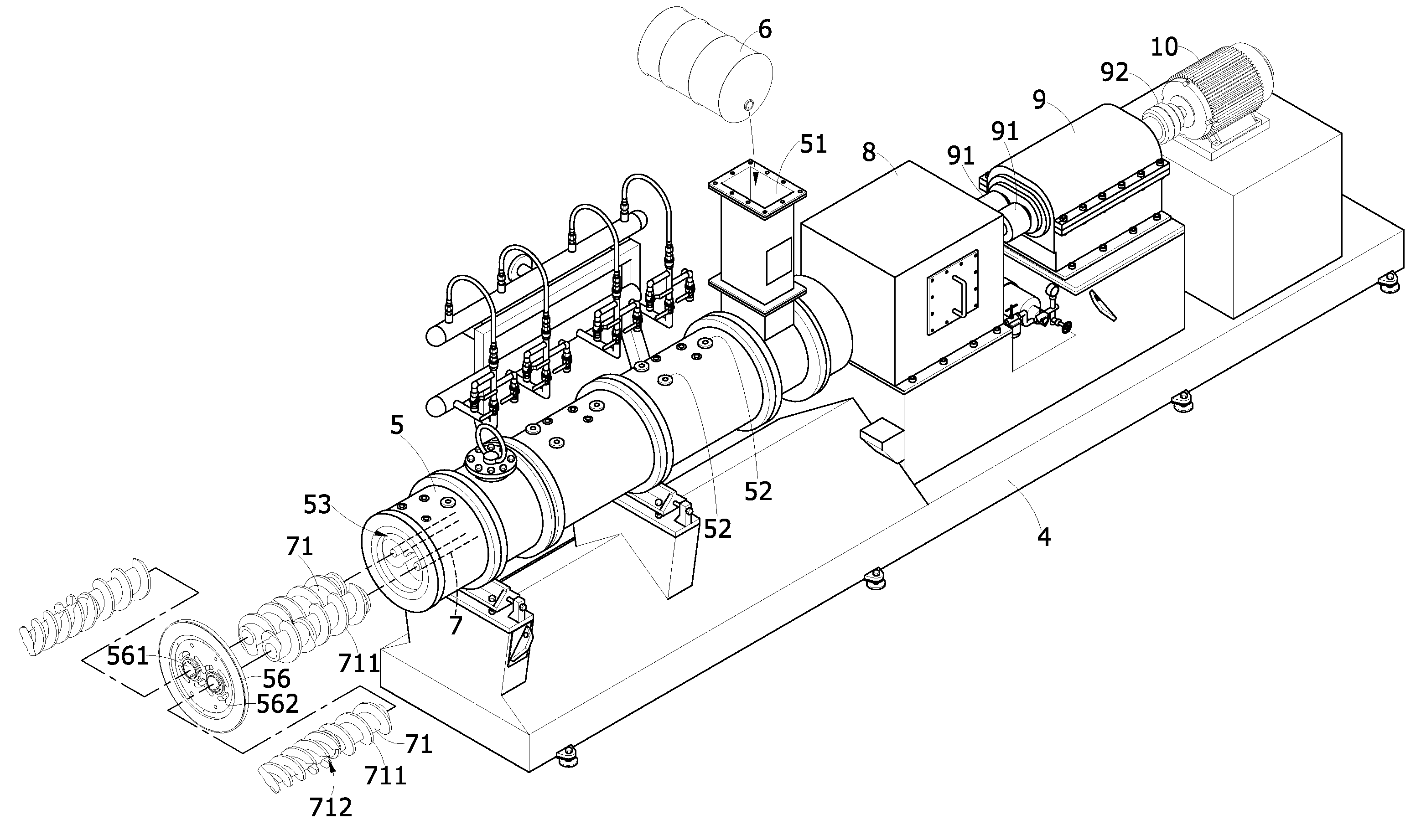
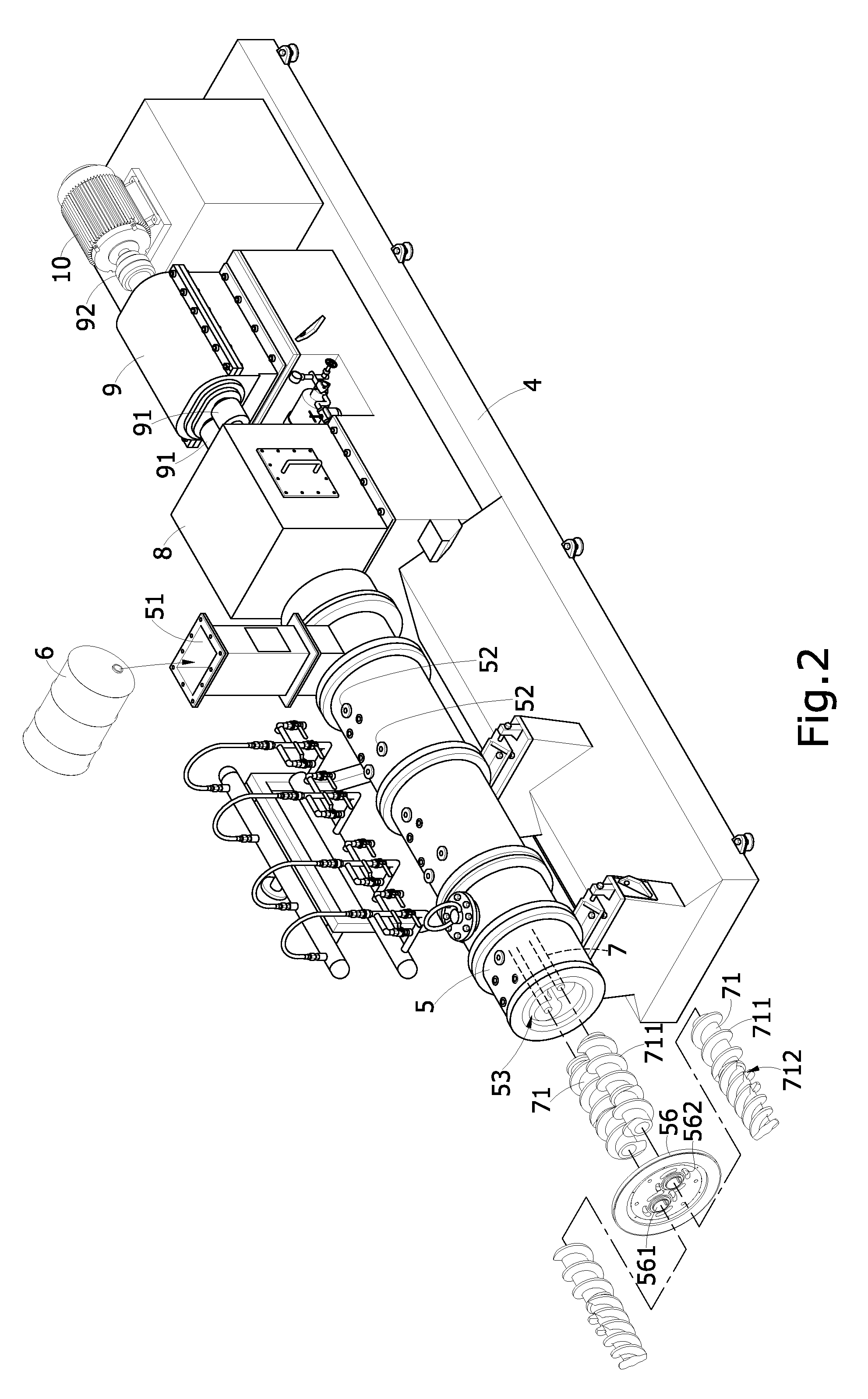
[0023]With reference to FIGS. 2-7, the present invention provides a counter-rotating twin-screw extruder, which is composed of the following constituent components.

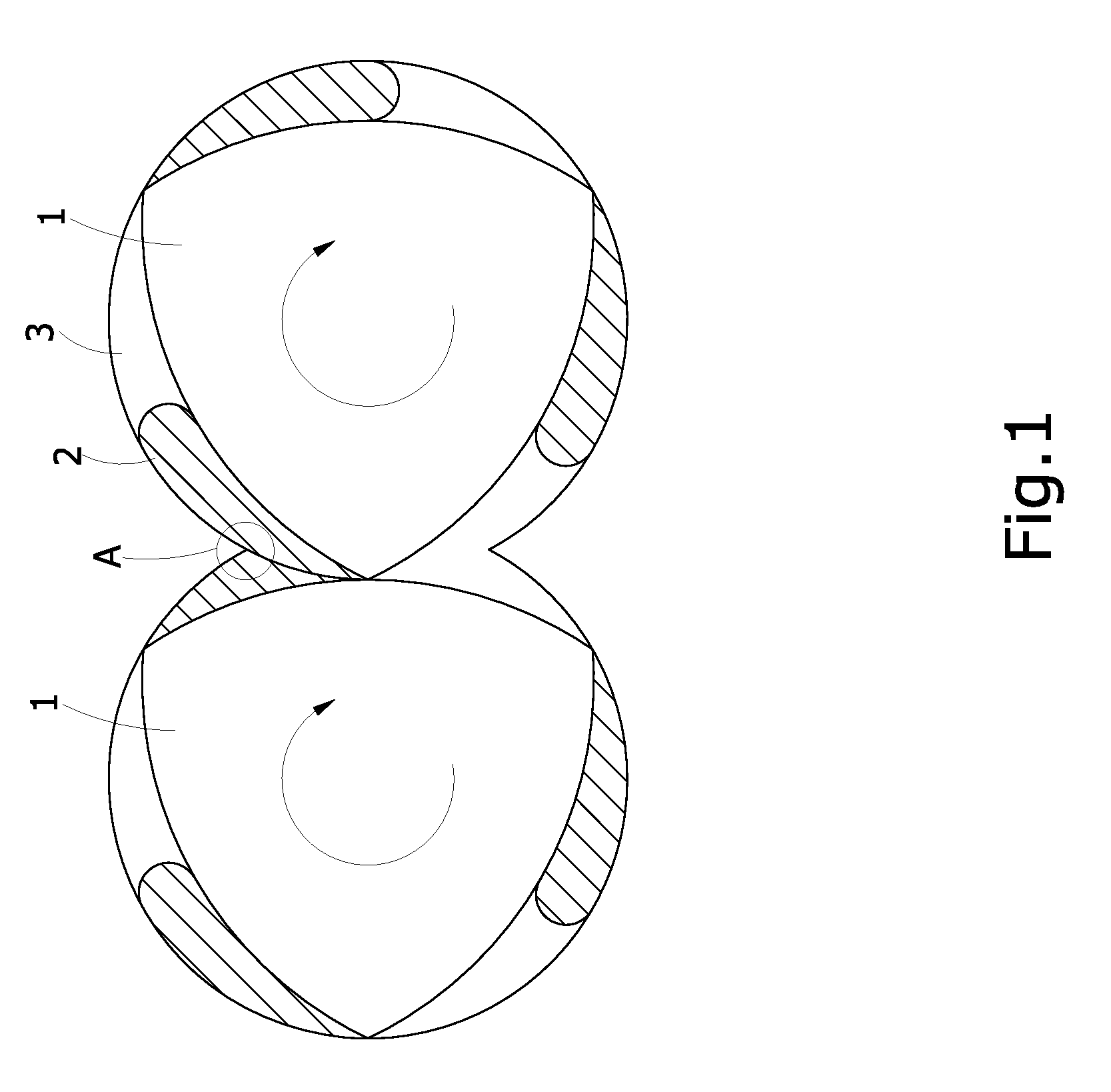
[0024]A casing barrel 5 is mounted on a frame 4. The outer wall of the casing barrel 5 set with at least one feeder 51 in the top for adding raw material 6 or additives and several heating holes 52 (which as shown in FIG. 3 is located in the top of the casing barrel 5) for importing the high temperature steam. The end of the casing barrel...


PUM

PropertyMeasurementUnit
speedaaaaaaaaaa
thermal energyaaaaaaaaaa
mechanical frictional thermal energyaaaaaaaaaa

Abstract

A counter-rotating twin screw extruder includes a motor that generates power through speed reduction of a gear box to directly or indirectly drive two symmetric screw shafts inside an enclosure barrel for synchronous but opposite rotations. Each screw shaft is fit with at least one section of screw and the two screws forms screw flight that are set in opposite directions and alternating each other. The barrel contains therein at least one flow restriction die. A bearing box is set between the barrel and the gear box. The purpose is to reduce unnecessarily induced mechanical energy during the conveyance of material and the advantages of using an independent bearing box are that manufacturing costs are reduced and consumption of energy is cut down. Parts wearing is reduced and durability is enhanced to eventually realize carbon reduction and energy saving.

Description

BACKGROUND OF THE INVENTION[0001](a) Field of the Invention[0002]The present invention relates to a food processing machine applicable to a slurry raw material, and more particularly to a counter-rotating twin screw extruder structure with two oppositely and alternately disposed screw blades.[0003](b) Description of the Prior Art[0004]In food industry, paste-like material, such as pet food, feeds or human foods, is utilized the co-rotating twin screw extruder which can effectively heat the starch in the material, appropriately mix, and then extrude the material to form the finished products.[0005]Referring to FIG. 1, the co-rotating twin screw extruder comprise with two symmetrical screws driven by motor either directly or indirectly in the barrel casing. The two screws can rotate synchronously in the same direction, either clockwise or counterclockwise. The screw surface set with alternating screw flight. As shown in the drawing, when the co-rotating twin-screw extruder operates, t...

Claims


Application Information

Patent Timeline
Patent Type & Authority Applications(United States)
IPC IPC(8): B29B13/02B28B17/02B29C48/41B29C48/52
CPCB01F7/085B01F15/00928B01F2215/0014B29C47/0011B29C47/6062B29C47/40B29C47/627B29C47/6012B29C47/6018B29C47/0801B29C48/04B29C48/252B29C48/52B29C48/53B29C48/575B29C48/655B29C48/41B29C48/405B01F27/723B01F35/56B01F2101/06
Inventor CHANG, SHOU-CHIH
Owner AVANTRON MICRO CO LTD
Why Eureka
Try Eureka