Reactor employing high-temperature air combustion technology

a combustion technology and high-temperature air technology, applied in the direction of combustion control, combustion types, furnaces, etc., can solve the problems of difficult to heat such a large amount of low-caloric fuel gas to a high temperature, large amount of low-caloric fuel gas is needed, and insufficient low-caloric fuel gas to produce high-temperature air combustion state. achieve the effect of increasing the reactor performan

Inactive Publication Date: 2010-06-10
CHIYODA CORP +1
View PDF5 Cites 6 Cited by
  • Summary
  • Abstract
  • Description
  • Claims
  • Application Information

AI Technical Summary

Benefits of technology

[0019]In the present invention, the pre-combustion air may be heated with heat of the combustion exhaust gas discharged from the combustion air supply apparatus of alternating heat exchange. Thus, not cold pre-combustion air, but heated pre-combustion air may be supplied into the combustion chamber, thereby increasing the reactor performance. Specifically, a pre-combustion air passage through which the pre-combustion air passes maybe provided between two flow passages arranged between the two vent openings and two of the regenerating means in such a manner that thermal transfer may be enabled or allowed between the pre-combustion air passage and the two flow passages.

Problems solved by technology

However, the low-caloric fuel gas is not enough to produce a high-temperature air combustion state.
However, when the low-caloric fuel gas is used as fuel gas, a large amount of the low-caloric fuel gas is needed and it is difficult to heat such a large amount of the low-caloric fuel gas to a high temperature.
Thus, it is hard to use the low-caloric gas in conventional fuel gas combustion apparatuses.

Method used


Image

  • Reactor employing high-temperature air combustion technology
  • Reactor employing high-temperature air combustion technology
  • Reactor employing high-temperature air combustion technology

Examples


Embodiment Construction

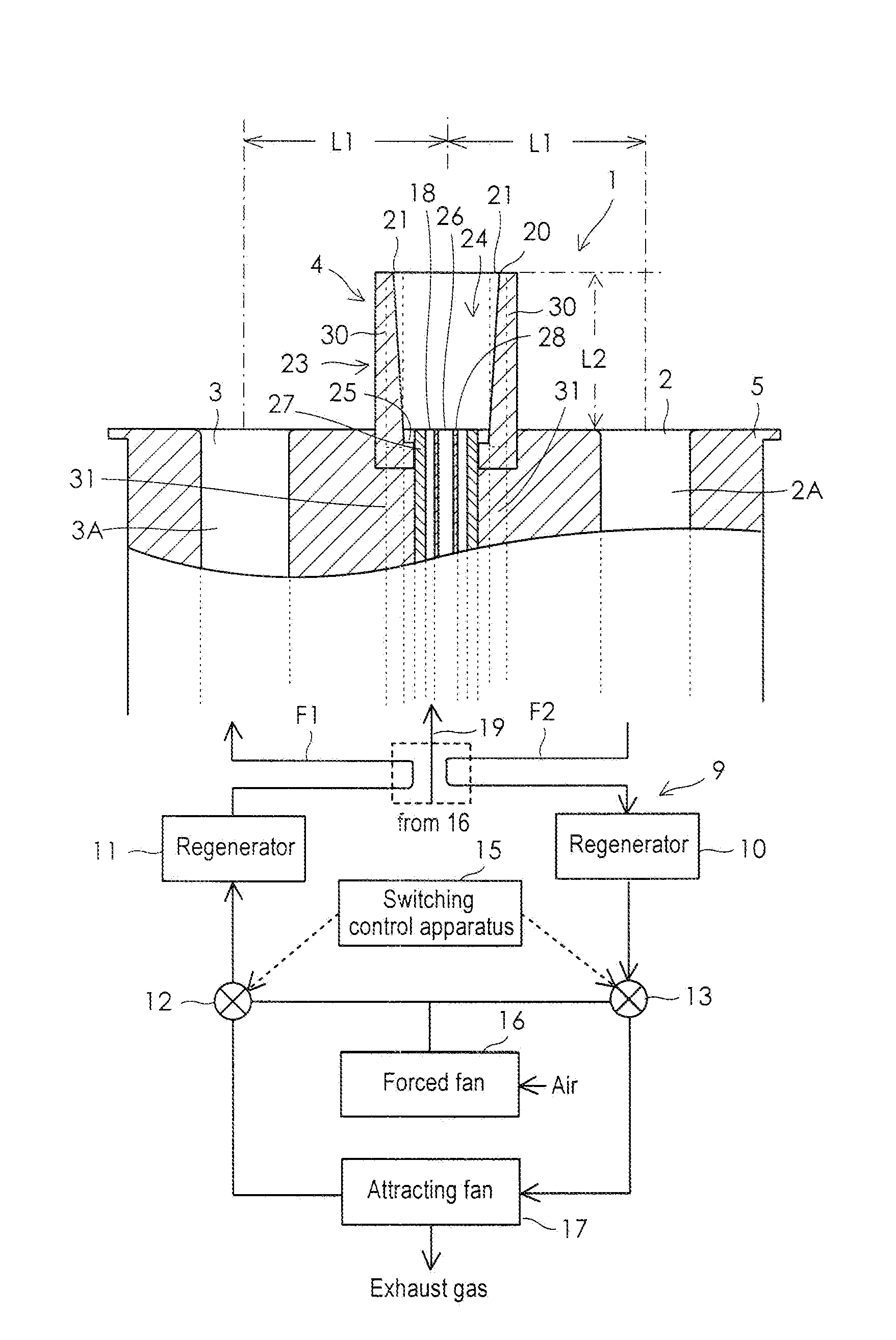
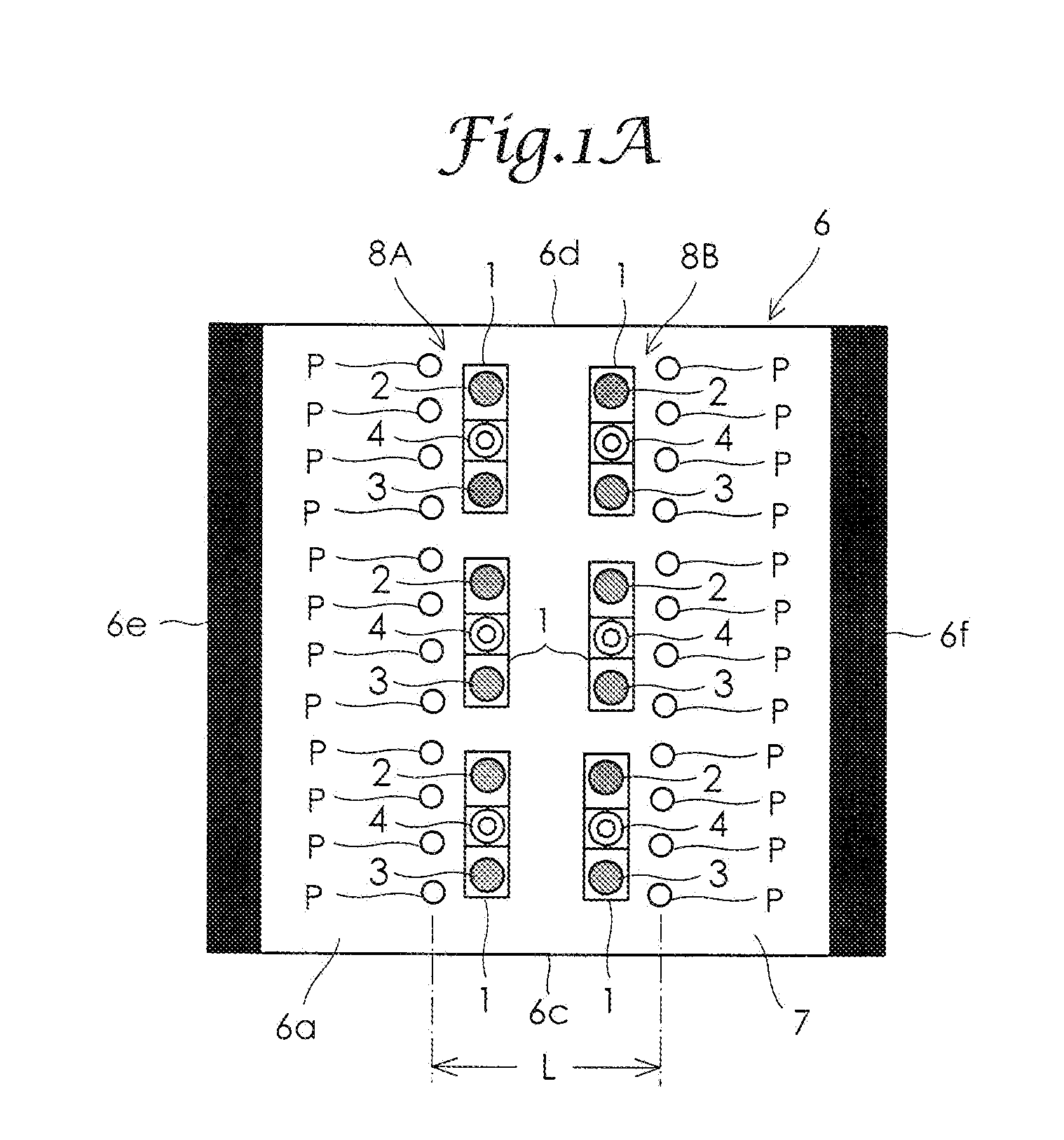
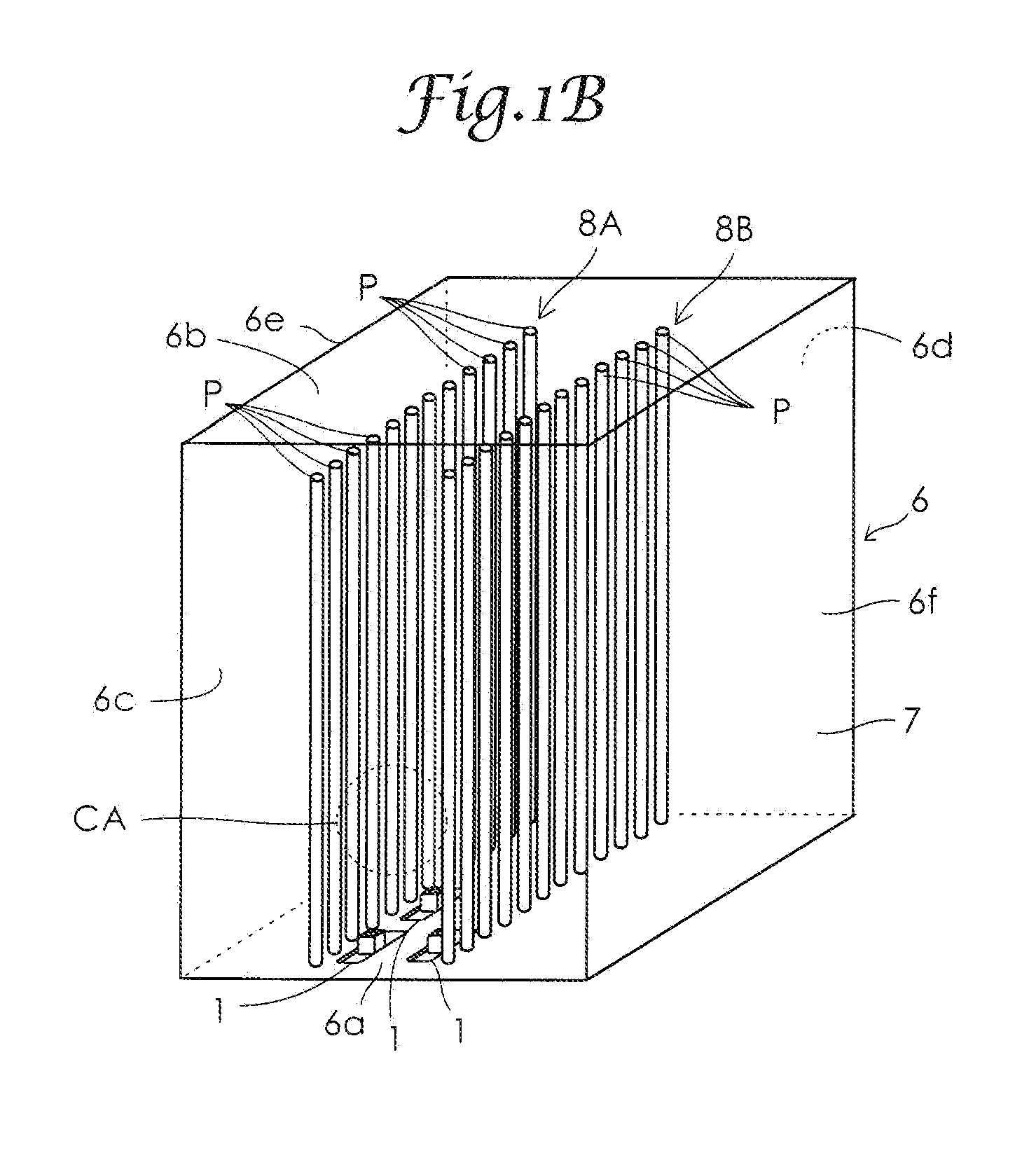
[0028]An embodiment of the present invention will now be described hereinbelow with reference to accompanying drawings. FIGS. 1A and 1B each show an example arrangement of a composite assembly 1 having a burner and vent openings, and reaction pipes P in a reactor when a fuel gas combustion apparatus is applied to a reactor. FIG. 2 is a top plan view of the composite assembly 1 having a burner and vent openings. FIG. 3 is a partial perspective view of the composite assembly 1 having a burner and vent openings. The composite assembly 1 having a burner and vent openings includes two vent openings 2, 3 that are used as a combustion exhaust gas discharge port and a high-temperature air supply port, and a burner assembly 4. The vent openings 2, 3 and the burner assembly 4 are combined in structure and supported by a fireproof structural member 5.

[0029]In FIGS. 1A and 1B, a reactor body is designated at a reference numeral 6, including a combustion chamber 7 therein. The reactor body 6 inc...


PUM


Abstract

In a burning air feeding device (9) of alternating heat-exchanging type, the feed of burning air and the discharge of a burned exhaust gas are performed at the speeds of 80 to 200 m/sec. A burner structure (4) is constituted such that a low-calorie fuel gas is preheated with the heat of a precombustion high-calorie fuel gas till the low-calorie fuel gas reaches a mixing starting zone (CA), and such that the precombustion high-calorie fuel gas and the low-calorie fuel gas are burned together in the mixing starting zone (CA). The sum (Q1+Q2) of an air quantity (Q1) fed from the hot air feeding ports of a plurality of fuel gas burning devices and an air quantity (Q2) of a precombustion air to be mixed with the high-calorie fuel gas in the plural fuel gas burning devices is set to 1.02 to 1.10 times as high as the stoichiometric air quantity (Qs) necessary for the combustion, and the ratio (Q2/(Q1+Q2)) is set within the range of 0.011 to 0.047.

Description

TECHNICAL FIELD[0001]The present invention relates to a reactor employing high-temperature air combustion technology and a fuel gas combustion apparatus suitable for use in the reactor.BACKGROUND ART[0002]Japanese Patent Application Publication No. 2005-46753 (JP2005-46753A) shows a conventional reactor that uses high-temperature air combustion technology. A fuel gas combustion apparatus used in a reactor employing high-temperature air combustion technology includes a burner assembly that injects fuel gas into a combustion chamber and a combustion air supply apparatus of alternating heat exchange type (hereinafter sometimes referred to simply as a combustion air supply apparatus). Japanese Patent Application Publication No. 10-205743 (JP10-205743A) shows a combustion apparatus that burns low-caloric fuel gas such as blast furnace gas and fart by heating the gas with a regenerator that has air permeability and is provided in the combustion air supply apparatus for heat exchange. The ...

Claims


Application Information

Patent Timeline
Patent Type & Authority Applications(United States)
IPC IPC(8): F23D14/66
CPCF23C6/047F23C2201/301F23N2037/08F23L15/02F23N2037/02F23D14/66F23N2237/02F23N2237/08Y02E20/34F23C1/00F23D17/00
Inventor MIKURIYA, TOMOYUKIYOSHIOKA, TOSHIAKIKAWARATA, RYOICHIWATANABE, EIJIONDA, NOBUHIRONIKKUNI, TAKEOWAKAMATSU, SHUHEIMOCHIDA, SUSUMUARAAKE, TADAHIRONAKAMURA, HIROYUKI
Owner CHIYODA CORP
Why Eureka
Try Eureka