Coagulation system

a coagulation system and coagulation technology, applied in the field of coagulation system, can solve the problems of tissue worth preservation, retinal pigment epithelium destruction, photoreceptor layer location, etc., and achieve the effect of rapid electrical influence of light beam

Inactive Publication Date: 2010-06-10
CARL ZEISS MEDITEC AG
View PDF27 Cites 17 Cited by
  • Summary
  • Abstract
  • Description
  • Claims
  • Application Information

AI Technical Summary

Benefits of technology

[0026]When switched on, the damper fitted into the resonator prevents the reflection of light which is emitted. No radiation is thereby delivered.
[0027]A selector which can switch very quickly (<10 ns) between blocking and letting through is preferably used as the acousto-optical modulator. An optical grid at which the light beam is diffracted is preferably generated in a transparent solid. Particularly preferably, the sound waves responsible for it are generated electrically via the piezo effect. A very rapid electrical influencing of the light beam is thereby possible.
[0028]A material which has a junction for the desired wavelength with a basic state that is normally occupied is preferably used as saturable absorber. Integrated in the laser, this material preferably absorbs some of the laser radiation. If the absorber becomes saturated, many states are thus stimulated, the absorption preferably falls, the quality of the resonator exceeds the lasing threshold and laser activity occurs for a short time.

Problems solved by technology

However, a disadvantage with the devices described in the two published documents is that, during their use, tissue which is worth preserving, in particular the photoreceptor layer located in the direction of the beam in front of the retinal pigment epithelium, is destroyed.

Method used


Image

  • Coagulation system
  • Coagulation system

Examples


Embodiment Construction

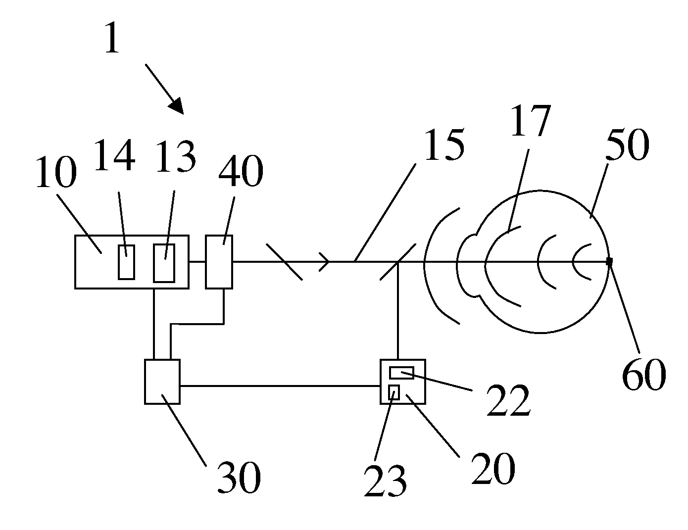
[0074]A coagulation system 1 according to the invention is represented in FIG. 1. The coagulation system 1 has a laser 10 with an acousto-optic modulator 13 and a resonator 14, to the output end of which an interrupter 40 is attached. Both the laser 10 and the interrupter 40 are connected to a controller 30. The controller 30 is in turn connected to a detector 20. When the laser 10 is switched on the laser 10 emits a working beam 15. The working beam 15 is targeted at the treatment zone 60 of a retina 50 of a human eye. The working beam is reflected by the retina 50 as a spherical wave 17. A part of the spherical wave 17 is redirected to the detector 20. In a confocal arrangement of the detector 20 which is targeted at the treatment zone 60, the indirectly back-scattered laser light or fluorescent light is detected with a diaphragm ring.

[0075]The laser 10 alternatively emits radiation with one wavelength or with up to four different wavelengths. The acousto-optic modulator 13 switch...


PUM


Abstract

A coagulation system for the coagulation of organic tissue includes a laser configured to emit a working beam; an interrupter configured to at least partially interrupt the working beam; a controller configured to activate the interrupter; and a detector configured to detect a signal corresponding to a degree of coagulation or alteration of the tissue and to transmit a detection of the signal to the controller, the detector including a dimension meter.

Description

[0001]This is a U.S. National Phase Application under 35 U.S.C. §171 of PCT / EP2008 / 000834, filed on Feb. 1, 2008, which claims priority to German Application No. DE 102007005699.2, filed on Feb. 5, 2007. The International Application was published in German on Aug. 14, 2008 as WO 2008 / 095659 under PCT article 21(2).[0002]The invention relates to a coagulation system for the coagulation of organic tissues.BACKGROUND[0003]Photocoagulation was first used at the end of the 1940s by means of the focused light of an axial high-pressure lamp to treat various diseases of the retina—for example diabetic retinopathy. By absorbing the laser beam particularly in the pigment epithelium, a layer located in the retina and bearing a dark pigment, in particular melanin, the retina is heated and coagulated. The metabolism is thereby focused on the still healthy areas of the retina. In addition, biochemical cofactors are stimulated. The course of the disease is thus clearly slowed or stopped.[0004]A p...

Claims


Application Information

Patent Timeline
Patent Type & Authority Applications(United States)
IPC IPC(8): A61F9/008A61B18/20
CPCA61F9/008A61F9/00817A61F9/00821A61F2009/00897A61F2009/00863A61F2009/00882A61F2009/00851
Inventor ZIMARE, DIEGODICK, MANFRED
Owner CARL ZEISS MEDITEC AG
Why Eureka
Try Eureka