Dental modeling system and method

a technology of dental modeling and model, applied in the field of dental modeling system and method, can solve the problems of insufficient precision in achieving accurate and precise tracking of tooth movement, difficult implementation in a practical manner, and insufficiently precise current techniques

Active Publication Date: 2010-06-10
HULTGREN DENTAL TECH LLC +1
View PDF13 Cites 73 Cited by
  • Summary
  • Abstract
  • Description
  • Claims
  • Application Information

AI Technical Summary

Benefits of technology

[0014]In creating an electronic virtual model, a casting of the patient's teeth is taken and a plaster model created. A scanner is used to digitize a three dimensional image of the patient's mouth for modeling. Alternatively, three dimensional high resolution digital scanners, such as CT scanners, intra-oral scanners, cone beam scanners or other digital capture devices may scan the patient's facial structure to create a three dimensional virtual model. A computer database stores the digital image and the image may be viewed as a three dimensional virtual model that may be manipulated on the computer screen. Moreover, the system provides for separating the teeth into discrete elements for modeling movement of an individual tooth and for modeling movement of all teeth to help in providing proper diagnosis for treatment and correction. The images may be manipulated to model projected growth or movement over time.
[0015]According to the present invention, modeling of tooth movement is accomplished by identifying an instant center of rotation for a particular tooth or other structure of the patient's jaw. The movement that the tooth would follow at that point in time is an arc centered about the instant center of rotation. The instant center of rotation can be plotted in three dimensions so that the model tooth movement follows the surface of an imaginary sphere centered about the instant center of rotation. As the image is digitized, the teeth or other structures and their respective instant centers of rotation can be mathematically represented with a set of coordinates so that the plotting of movement is accomplished with great precision. Locating the instant center of rotation is accomplished utilizing a number of factors based on the patient's tooth and jaw physiology and the knowledge and experience of the dental practitioner. It can be appreciated that the instant center of rotation varies from patient to patient and an instant center may be above or below the position of the tooth as well as to one side or the other, or forward or behind a tooth. The position may be quite close to the tooth or may approach infinity so that the virtual tooth substantially models straight line movement.

Problems solved by technology

However, studies and modeling reveal that tooth movement and growth is not usually truly linearly translational.
Although such models have proven to be successful in providing guidance for predicting tooth growth and movement, implementation in a practical manner has proven difficult.
Current techniques do not provide for accurately tracking tooth movement with sufficient precision and their relationship to the tooth's reference points.
While such markers provide for improved modeling and tracking, the insertion and placement of such markers and tracking of the markers relative to one another is intrusive and only allows tracking of the marker rather than the entire tooth.
A further problem with such markers and / or landmarks is the precision possible in tracking the changes in position.
The insertion and removal of markers is intrusive and inconvenient for the patient, requiring an additional procedure.
While such methods do provide for tracking of position and changes, the accuracy of such methods is decreased due to quality and resolution available for the images and the inaccuracy from manually outlining and precisely locating the markers and / or structural landmarks.
As the accuracy and precision are critical for predicting small movements and in locating instant centers of rotation, such tools may not be an acceptable simulator of the teeth and their movement.
Due to the precise measurements and the small distances involved, even minor errors can have a drastic adverse affect on the position of an instant center of rotation and therefore, the entire model and movement simulation, increasing the possibility for improper diagnosis and treatment.
The digital EMODEL™ digital model system provides a precise high resolution digital map of the teeth and gums, but its use has been limited in creating prostheses.
Such three dimensional digital images have been used as a starting point in treatment, but have not been used to project and simulate growth and movement.

Method used


Image

  • Dental modeling system and method
  • Dental modeling system and method
  • Dental modeling system and method

Examples


Embodiment Construction

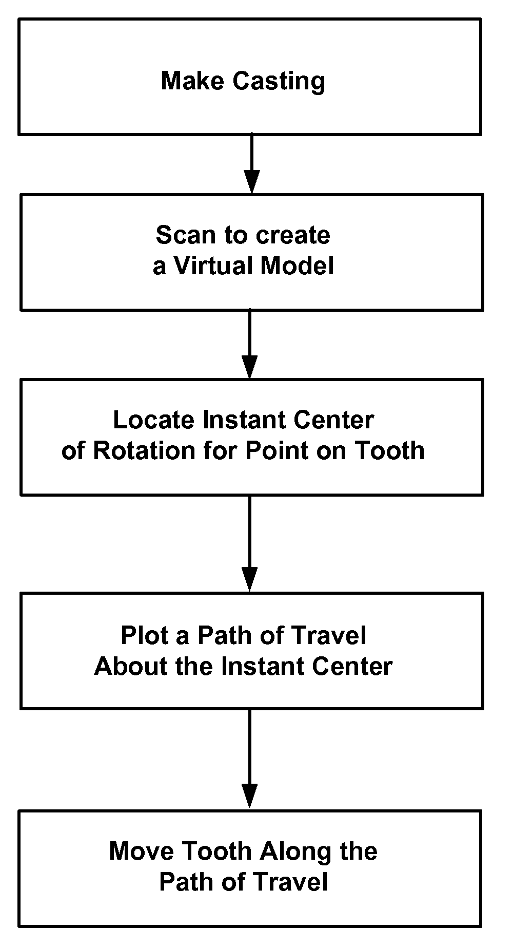
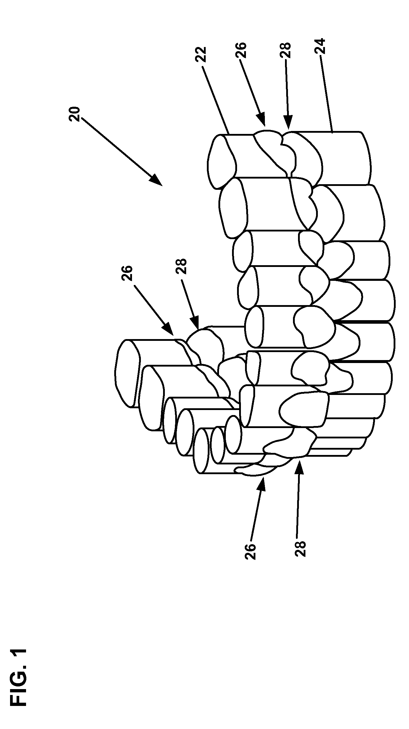
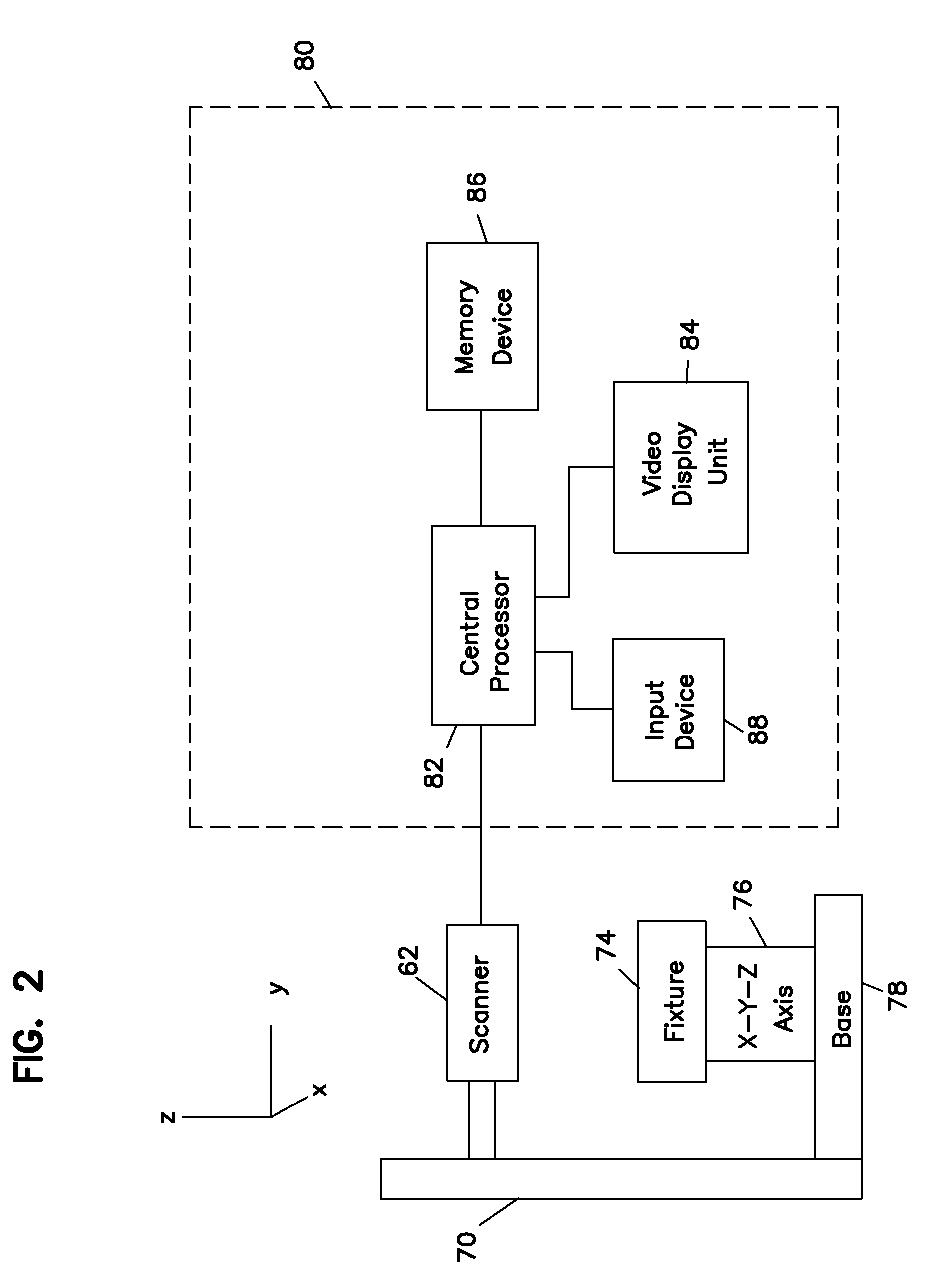
[0030]Referring now to the drawings, and in particular to FIG. 1, there is shown a digital image of a patient's dentition 20 including an upper arch having a portion of the upper gums 22, and the exposed surfaces of the upper teeth 26. In a similar manner, a lower arch including a portion of the teeth and lower gums 24 is also created in a digitized model along with the exposed upper surfaces of the lower teeth 28. Such an image of the dentition 20 is digitized and provides a virtual three dimensional image of the patient's teeth for diagnosis, treatment and correction. Such a method and system for creating such a virtual image of the patient's mouth is shown and described in U.S. Pat. No. 6,579,059, incorporated herein by reference. One method of creating digital images is taking a casting of the patient's teeth and creating a plaster model and scanning the plaster cast. The digitizing system 70 is shown in FIG. 2 and includes a scanner 72 that passes a laser over the plaster model...


PUM


Abstract

A method for simulating tooth movement utilizes electronic modeling to represent the teeth. Instant centers of rotation are determined and projected paths of movement are plotted. The electronic model provides improved precision and provides a method for simulating movement in three dimensions. The movement from growth and / or correction is shown with the electronic model. The simulation provides for improved correction.

Description

BACKGROUND OF THE INVENTION[0001]1. Field of the Invention[0002]The present invention relates to a method and system for simulating movement of a patient's jaw and teeth.[0003]2. Description of the Prior Art[0004]In the field of orthodontics, simulation is important for treatment and correction. If the manner in which the teeth and jaw may form and grow is known, the dental practitioner is better able to diagnose problems and identify potential problems. In addition, the limits of moving teeth through braces and other correction techniques become more apparent and treatment may be carried out with more precision and greater chance of success.[0005]Prior simulation techniques consisted of the dental practitioner observing the patient's teeth and utilizing the practitioner's knowledge and judgment to predict how the teeth would move by estimating the effects of braces and other corrective techniques. Although usually successful in correcting at least some of the structural problems, g...

Claims


Application Information

Patent Timeline
Patent Type & Authority Applications(United States)
IPC IPC(8): G06G7/60G06F17/50G06F17/10
CPCA61C7/00A61C9/0053A61C7/002
Inventor HULTGREN, BRUCE W.MARSHALL, MICHAEL C.
Owner HULTGREN DENTAL TECH LLC
Why Eureka
Try Eureka