Antenna apparatus and radio communication apparatus

a radio communication and antenna technology, applied in the direction of radiating elements, elongated active element feed, resonance antenna, etc., can solve the problem of lack of practicability of the antenna apparatus, and achieve the effect of increasing the number of resonance frequencies

Inactive Publication Date: 2010-06-17
MURATA MFG CO LTD
View PDF4 Cites 23 Cited by
  • Summary
  • Abstract
  • Description
  • Claims
  • Application Information

AI Technical Summary

Benefits of technology

[0026]The invention according to another embodiment provides the antenna apparatus in which one or more branched radiation electrodes that branch off from the loop-shaped radiation electrode near the first reactance circuit are disposed. As a result, it is possible to increase the number of resonance frequencies by increasing the number of branched radiation electrodes.
[0027]The invention according to another embodiment provides the antenna apparatus in which the first reactance circuit and the second reactance circuit are disposed on only a side surface of the dielectric substrate. As a result, it is possible to dispose the radiation electrode at an allowable antenna height.

Problems solved by technology

However, the above-described antenna apparatuses have the following problems.
The antenna apparatus therefore lacks in practicability.

Method used


Image

  • Antenna apparatus and radio communication apparatus
  • Antenna apparatus and radio communication apparatus
  • Antenna apparatus and radio communication apparatus

Examples


first embodiment

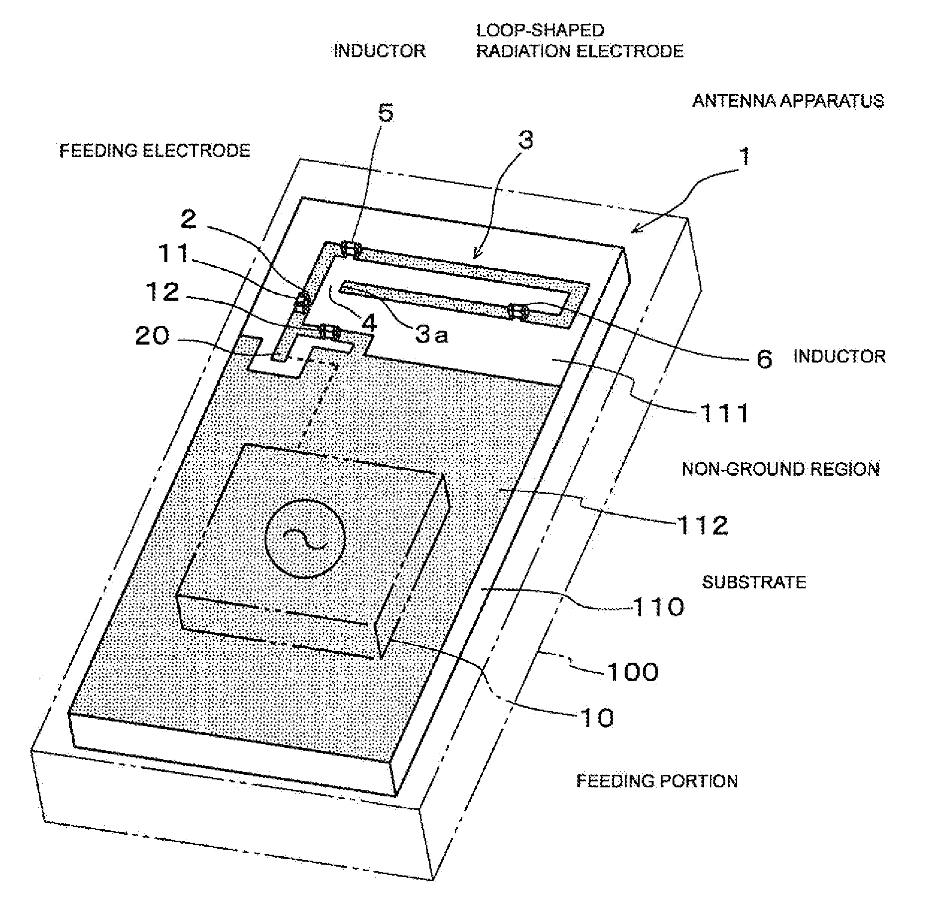
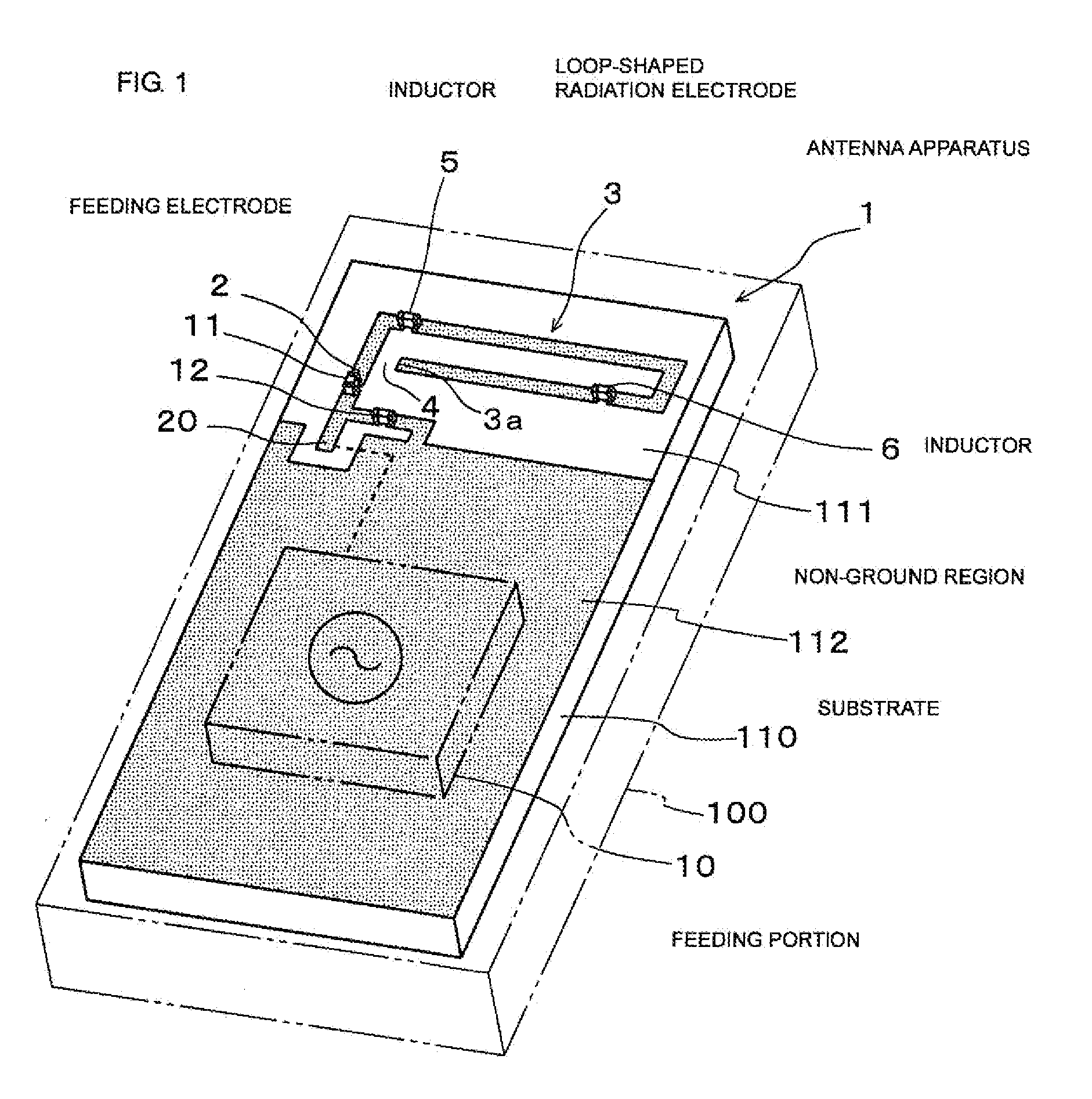
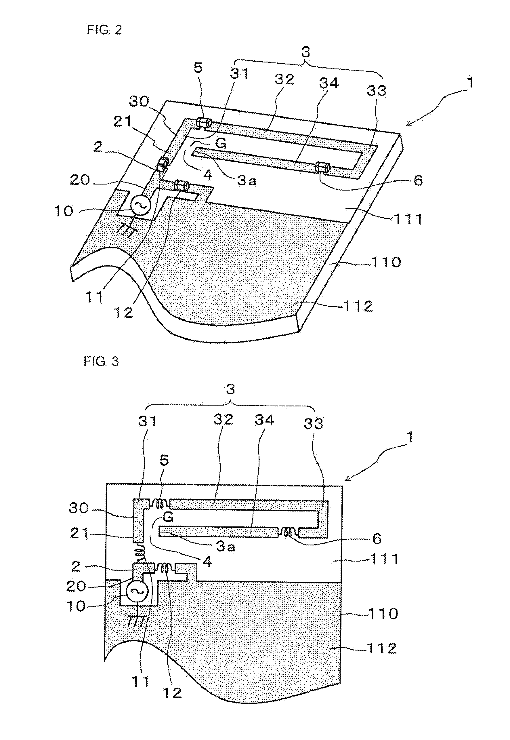
[0056]FIG. 1 is a schematic perspective view of an antenna apparatus according to the present invention included in a radio communication apparatus. FIG. 2 is an enlarged perspective view of the antenna apparatus. FIG. 3 is a schematic plan view of the antenna apparatus.

[0057]As illustrated in FIG. 1, this radio communication apparatus is a mobile telephone, and includes an antenna apparatus 1 according to the first embodiment of the present invention in a casing 100 thereof. The radio communication apparatus also includes a keyboard, a microphone, a speaker, a liquid crystal panel, and various electronic circuits such as a control unit. However, since these components have known mechanisms, the description thereof and the illustration thereof will be therefore omitted. Accordingly, the antenna apparatus 1 and the mechanism of the antenna apparatus 1 will be described.

[0058]The antenna apparatus 1 is a monopole antenna operable in a basic mode and a higher mode, and includes a feedi...

fifth embodiment

[0098]An antenna apparatus differs from an antenna apparatuses according to the above-described embodiments in that the first reactance circuit is formed of a series circuit or a parallel circuit including an inductor and a capacitor. The first reactance circuit 5 is a circuit for passing a current of a resonance frequency in the basic mode and blocking a current of a resonance frequency in the higher mode. Accordingly, the first reactance circuit 5 is required to have a low reactance value at a low frequency and a large reactance value at a high frequency.

[0099]In the above-described embodiments, the first reactance circuit 5 is formed of a single inductor, that is, the inductor 5, in which a reactance value varies slightly in accordance with the change in frequency. Accordingly, as indicated by a reactance curve V1 in FIG. 17, a desired reactance value of 100Ω can be obtained at a frequency of approximately 500 MHz in the basic mode, but a reactance value of 300Ω that is an insuf...


PUM


Abstract

An antenna apparatus and a radio communication apparatus are capable of separately controlling a resonance frequency in a basic mode and a resonance frequency in a higher mode and have a wide bandwidth in which the resonance frequency in the basic mode is variable. The antenna apparatus includes a feeding electrode 2, a loop-shaped radiation electrode 3, a capacitance portion 4, and inductors 5 and 6. The capacitance portion 4 is formed by a gap between an open end 3a of the loop-shaped radiation electrode 3 and the feeding electrode 2. The inductor 5 is disposed at a position where a large current is obtained in the basic mode and a small current is obtained in the higher mode. The inductor 6 is disposed at a position where a large current is obtained in the higher mode and a small current is obtained in the basic mode.

Description

CROSS REFERENCE TO RELATED APPLICATIONS[0001]The present application is a continuation of International Application No. PCT / JP2008 / 060962, filed Jun. 16, 2008, which claims priority to Japanese Patent Application No. 2007-217968 filed Aug. 24, 2007, the entire contents of each of these applications being incorporated herein by reference in their entirety.BACKGROUND OF THE INVENTION[0002]1. Field of the Invention[0003]The present invention relates to a variable-frequency antenna apparatus installed in a mobile telephone or the like and a radio communication apparatus.[0004]2. Description of the Related Art[0005]Japanese Unexamined Patent Application Publication No. 2002-158529, Japanese Unexamined Patent Application Publication No. 2005-318336, and WO 2004 / 109850 disclose antenna apparatuses.[0006]In the antenna apparatus disclosed in Japanese Unexamined Patent Application Publication No. 2002-158529, the open end of a loop-shaped radiation electrode faces an electrode portion on the...

Claims


Application Information

Patent Timeline
Patent Type & Authority Applications(United States)
IPC IPC(8): H01Q1/00H01Q1/24H01Q1/38H01Q1/50H01Q5/10H01Q5/321H01Q9/14H01Q9/42
CPCH01Q1/243H01Q1/38H01Q5/321H01Q9/42H01Q9/145H01Q5/00
Inventor NAKANO, SHINICHIKAWAHATA, KAZUNARITUBAKI, NOBUHITOISHIZUKA, KENICHIFUJIEDA, SHIGEYUKI
Owner MURATA MFG CO LTD
Why Eureka
Try Eureka