Holographic Reconstruction system with a Tracking Device for the Reconstruction

a tracking device and reconstruction technology, applied in the field of holographic reconstruction systems, can solve the problems of only visible reconstruction without errors, difficult to be detected for the observer without any aids, and inability to compensate for disturbances through filtering

Active Publication Date: 2010-06-17
SEEREAL TECHNOLOGIES
View PDF14 Cites 38 Cited by
  • Summary
  • Abstract
  • Description
  • Claims
  • Application Information

AI Technical Summary

Benefits of technology

[0037]FIG. 2 shows a reconstruction system according to the international publication WO 2004 / 044659, on which the system according to the present invention is based, and which describes the effect of parasitic light points with example of an adjacent diffraction order for a single reconstructed object light point of the scene.

Problems solved by technology

However, a problem occurs if the known system encodes the holographic information for each object light point on the entire modulator surface of a two-dimensional spatial light modulator with a pixelated modulator cell structure, e.g. a liquid crystal display.
This disturbance cannot be compensated by way of filtering.
The two prior art reconstruction systems have the disadvantage that the reconstruction is only visible without errors from the visibility region VR, which lies in the focal plane FL.
The visibility region is of virtual nature and thus difficult to be detected for the observer without any aids.
Such tracking means are relatively complicated and exhibit optical elements which severely deform the propagating wave field prior to the reconstruction of the scene.
Consequently, aberrations and runtime errors with fluctuating portions occur.
Changing observer eye positions cause aberrations, such as spherical aberration, coma, field curvature, astigmatism and distortion, which are difficult to compensate due to their fluctuating portions.
These deformations cause the coincidence of the light waves in the visibility region to be disturbed and individual reconstructed object light points of the scene to be reconstructed at an incorrect position or in a blurred manner, so that the scene is represented in a distorted manner or, in extreme cases, individual objects of the scene in the visibility region are even missing.
Besides a relatively small reconstruction space for a reconstruction close to the focal plane FL, that prior art reconstruction system has the disadvantage, compared to the former one, that it only uses a greatly limited number of all available modulator cells of the light modulator.
Because a fix background is missing, the system is little suitable for the reconstruction of video scenes with objects in multiple spatial depths.

Method used


Image

  • Holographic Reconstruction system with a Tracking Device for the Reconstruction
  • Holographic Reconstruction system with a Tracking Device for the Reconstruction
  • Holographic Reconstruction system with a Tracking Device for the Reconstruction

Examples


Embodiment Construction

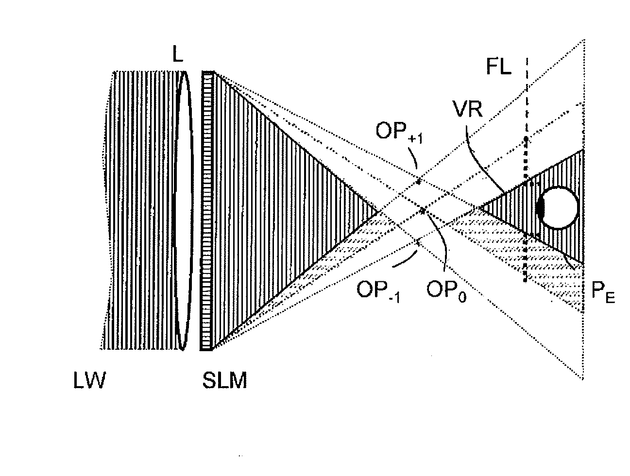
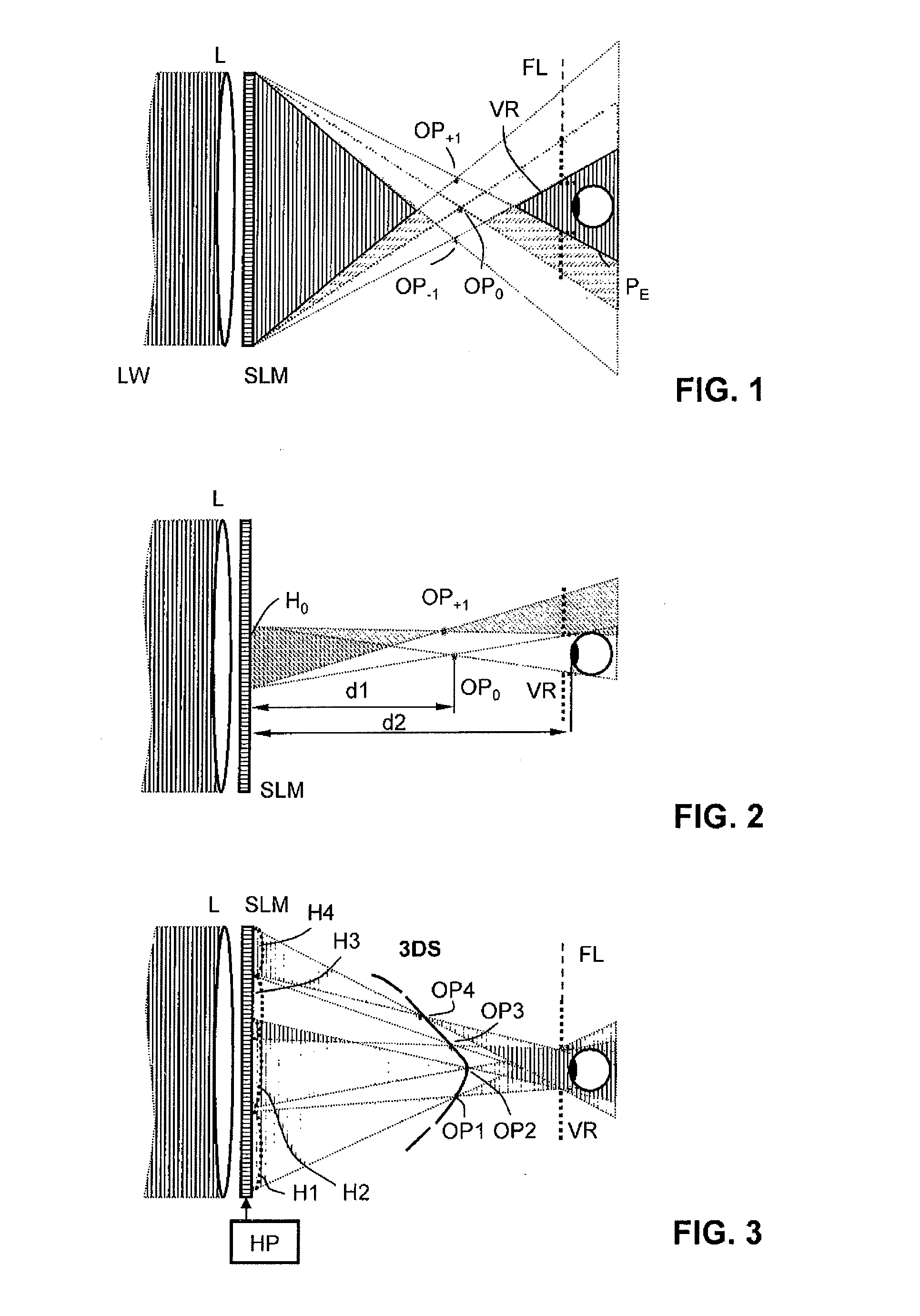
[0043]The function of the reconstruction system according to the present invention can be explained with the help of lenses and prisms which are encoded as structure of focussing lens functions and optical prism functions on the cell structure of the spatial light modulator means by the hologram processor when computing the video holograms.

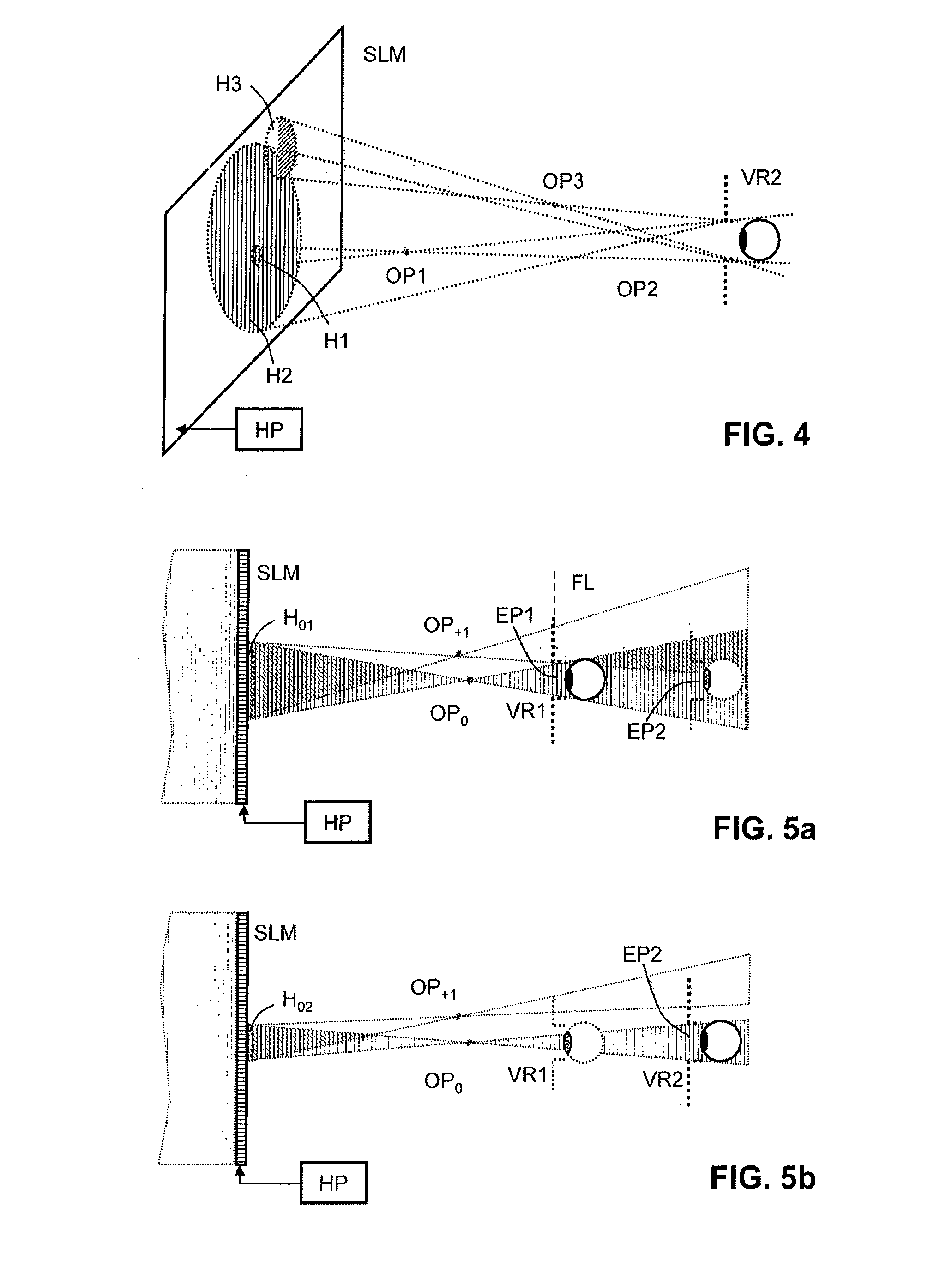
[0044]FIG. 4 is a perspective view illustrating how the cell structure of the spatial light modulator SLM is encoded with the help of the example of object light points OP1 to OP3, which are selected as typical examples of a three-dimensional scene.

[0045]According to the known basic principle of the present invention, the hologram processor HP defines a hologram region H1 to H3 on the cell structure for each object light point OP1 to OP3 and computes a lens term and, if necessary, a prism term for each hologram region with the help of holographic information about the object light point. This means that each hologram region on the cell structure i...


PUM


Abstract

A holographic reconstruction system having spatial light modulators, an eye finder and a position control orients a propagating spatially modulated light wave field toward at least one eye position of an observer's eye, thereby reconstructing a scene in a three-dimensional manner and tracking the same during a position change of the eye position. Through Unobstructed lateral and axial movement of the observer head to arbitrary eye positions in a tracking region is enabled. The use of additional, planar optical components, which bring about optical aberrations during a position change of observer eyes, are prevented.

Description

FIELD OF THE INVENTION [0001]The present invention relates to a holographic reconstruction system where a propagating modulated light wave field, which propagates to at least one eye of an observer, reconstructs a scene three-dimensionally thus making it visible for said eye. The system comprises spatial light modulator means, an eye finder and a position controller in order to direct the propagating modulated light wave field with the holographic reconstruction at the eye position of at least one observer and to track said propagating modulated light wave field to the eye position if an observer changes his eye position. The present invention relates in particular to means for adjusting the axial distance of the eye position to the reconstruction system.[0002]The invention is independent of the way the holographic information is provided, and it can also be used in reconstruction systems which allow multiple observers to watch a holographically reconstructed video scene simultaneou...

Claims


Application Information

Patent Timeline
Patent Type & Authority Applications(United States)
IPC IPC(8): H04N13/00H04N7/18
CPCG03H2226/05G03H1/2294G03H1/0808G03H2001/0825G03H2210/36G03H2210/452G03H1/04G03H1/10
Inventor KROLL, BOSCHWERDTNER, ARMINOLAYA, JEAN-CHRISTOPHE
Owner SEEREAL TECHNOLOGIES
Why Eureka
Try Eureka