Optical system, exposure apparatus, and method of manufacturing electronic device

a technology of exposure apparatus and optical system, which is applied in the direction of mirrors, instruments, printers, etc., can solve the problems of deterioration of optical performance, image distortion, and inability to provide the aperture diaphragm at the optimal position, so as to improve the quality of image. , the effect of excellent optical performan

Active Publication Date: 2010-06-17
NIKON CORP
View PDF6 Cites 36 Cited by
  • Summary
  • Abstract
  • Description
  • Claims
  • Application Information

AI Technical Summary

Benefits of technology

[0016]According to the optical system concerning the first aspect of the present invention, the contour of the aperture formed by the aperture diaphragm has the three-dimensional shape. Therefore, the optical system can be adapted more appropriately to the actual pupil shape of the optical system, and thus it is possible to provide the optical system which is excellent in the optical performance.
[0017]According to the optical system concerning the second aspect of the present invention, the contour of the pupil plane of the optical system can be allowed to have the three-dimensional shape. Thus, it is possible to provide the optical system which is excellent in the optical performance.
[0018]According to the exposure apparatus concerning the present invention, a finer pattern can be formed more accurately, because the optical system or the aperture diaphragm of the present invention is used.

Problems solved by technology

However, such an aperture diaphragm is not provided at an optimum position in relation to respective orientations in the field.
For this reason, it is feared that the deterioration of the optical performance, which includes the distortion of the image, etc. might be caused when the image is projected onto the wafer.

Method used


Image

  • Optical system, exposure apparatus, and method of manufacturing electronic device
  • Optical system, exposure apparatus, and method of manufacturing electronic device
  • Optical system, exposure apparatus, and method of manufacturing electronic device

Examples


first embodiment

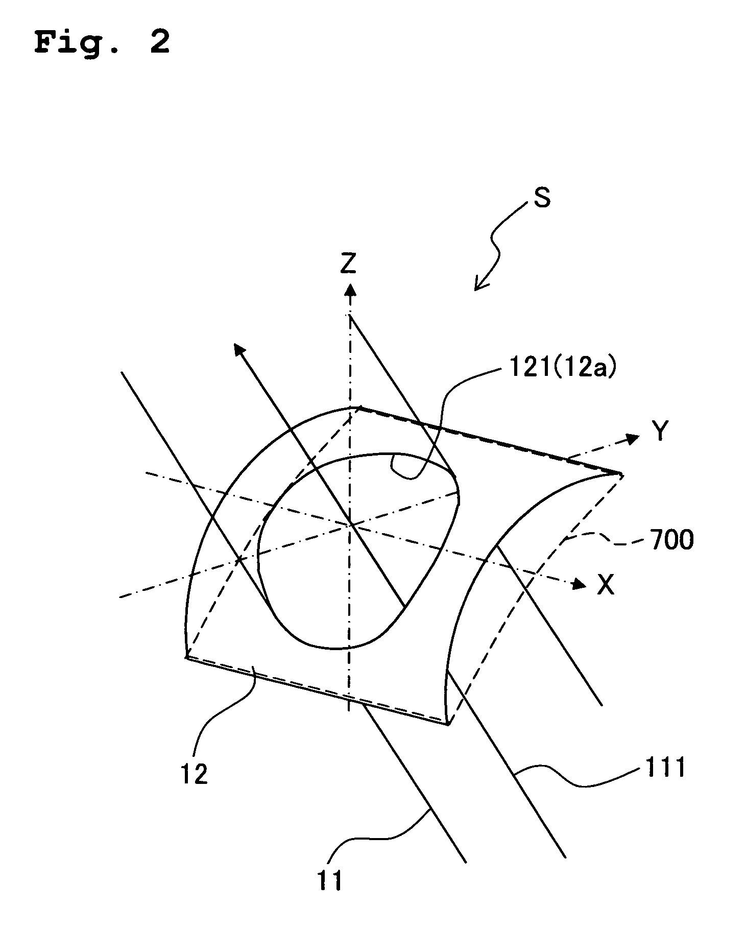
[0071]FIG. 2 shows a perspective view of the structure and the arrangement of the aperture diaphragm (NA diaphragm) according to a first embodiment of the present invention. FIG. 3 shows a perspective view of the structure of aperture diaphragm plates as well. The following assumption is affirmed in FIG. 2. That is, the Z axis extends in the optical axis direction (vertical direction when the projection optical system is placed vertically), the XY plane is a horizontal surface, the Y axis extends in the scanning direction, the X axis extends in the non-scanning direction, and the optical system is designed symmetrically in relation to the Y axis.

[0072]The aperture diaphragm S of this embodiment is constructed to include an aperture diaphragm plate 12. The aperture diaphragm plate 12 is constructed by providing an aperture 12a, having a predetermined shape, for example, an elliptical shape, for a plate-shaped member previously curved to provide a predetermined curved surface (three-d...

second embodiment

[0081]FIG. 5 shows a perspective view of the construction of an aperture diaphragm (NA diaphragm) according to a second embodiment of the present invention. FIG. 6 shows a side view of the same, and FIG. 7 shows a top view of the same. The aperture diaphragm S of this embodiment is provided as a variable aperture diaphragm of such a type that a plurality of first strip members ST1 and a plurality of second strip members ST2 are inserted in the ±X directions respectively with respect to the light flux 25 including a main light beam 225 passing through the pupil so as to form the contour of the aperture.

[0082]In the aperture diaphragm S of this embodiment, as shown in FIGS. 5 and 6, the plurality of (ten in FIGS. 5 and 6) first strip members ST1 (example of the first light shielding member) constructing a first variable light shielding member VR1 and the plurality of (ten in FIGS. 5 and 6) second strip members ST2 (example of the second light shielding member) constructing a second va...

third embodiment

[0118]FIG. 16 shows a perspective view of the construction of an aperture diaphragm (NA diaphragm) according to a third embodiment of the present invention. The aperture diaphragm S of this embodiment is a variable aperture diaphragm of such a type that the contour of the aperture is formed by inserting a plurality of substantially semicylindrical first light shielding members ST11 and a plurality of substantially semicylindrical second light shielding members ST21 in the ±Z directions with respect to a light flux 31 passing through the pupil (pupil of the projection optical system PL). In this embodiment, a main light beam 311 of a light flux 31 is inclined by a predetermined angle with respect to the optical axis AX (Z axis), and a pupil plane PP of the projection optical system PL is perpendicular to the optical axis of the projection optical system PL.

[0119]The aperture diaphragm S is such a device that the aperture portion SH, which has sizes corresponding to a plurality of NA'...


PUM


Abstract

An aperture diaphragm plate is provided to define a light flux on a pupil plane of an optical system or a plane or surface disposed in the vicinity of the pupil plane. An aperture, which is formed in the aperture diaphragm plate, has a three-dimensional shape corresponding to an optimum pupil shape of the optical system. It is possible to improve the imaging characteristic brought about by the optical system by providing the optimum pupil shape of the optical system.

Description

CROSS-REFERENCES TO RELATED APPLICATIONS[0001]This application claims the benefit of priority of Japanese Patent Application No. 2008-239478 filed on Sep. 18, 2008 and U.S. Provisional Application Ser. No. 61 / 136,704 filed on Sep. 26, 2008, the entire disclosures of which are incorporated herein by reference in their entireties.BACKGROUND OF THE INVENTION[0002]1. Field of the Invention[0003]The present invention relates to an aperture diaphragm which is arranged in an optical system, the optical system, and an exposure apparatus. The present invention is preferably usable for an optical system of an exposure apparatus which is used in the lithography step of producing a device including a liquid crystal display element, a semiconductor element, etc. The present invention also relates to a method for producing an electronic device using the exposure apparatus.[0004]2. Description of the Related Art[0005]In recent years, an exposure technique, which is using the EUV (Extreme Ultra-Vio...

Claims


Application Information

Patent Timeline
Patent Type & Authority Applications(United States)
IPC IPC(8): G03B27/72G02B7/00G02B5/08G02B26/02G03B27/32
CPCG02B5/005G03F7/7025G03F7/70091G02B17/0657
Inventor SHIRAISHI, MASAYUKIONO, TAKURO
Owner NIKON CORP
Why Eureka
Try Eureka