Method and Apparatus for Combining EUV Sources

Inactive Publication Date: 2010-06-17
NIKON CORP
View PDF7 Cites 2 Cited by
  • Summary
  • Abstract
  • Description
  • Claims
  • Application Information

AI Technical Summary

Benefits of technology

[0006]More specifically, the present invention provides a structure and method for combining two or more EUV (extreme ultra violet) sources for illumination of an EUV reticle, in a manner that counteracts the reduction of illumination power due to absorption of EUV light by the optical elements of the structure. In a preferred embodiment, the present invention uses certain aspects of a fly's eye illumination system to combine the source power in the pupil of the EUV illumination system, in a manner that increases the amount of light in the illumination system.

Problems solved by technology

Thus, an EUV lithography system tends to be strongly light limited by the optical elements of the system; hence the optical elements of the system can cause the power of the illumination source to be significantly reduced.

Method used


Image

  • Method and Apparatus for Combining EUV Sources
  • Method and Apparatus for Combining EUV Sources
  • Method and Apparatus for Combining EUV Sources

Examples


Embodiment Construction

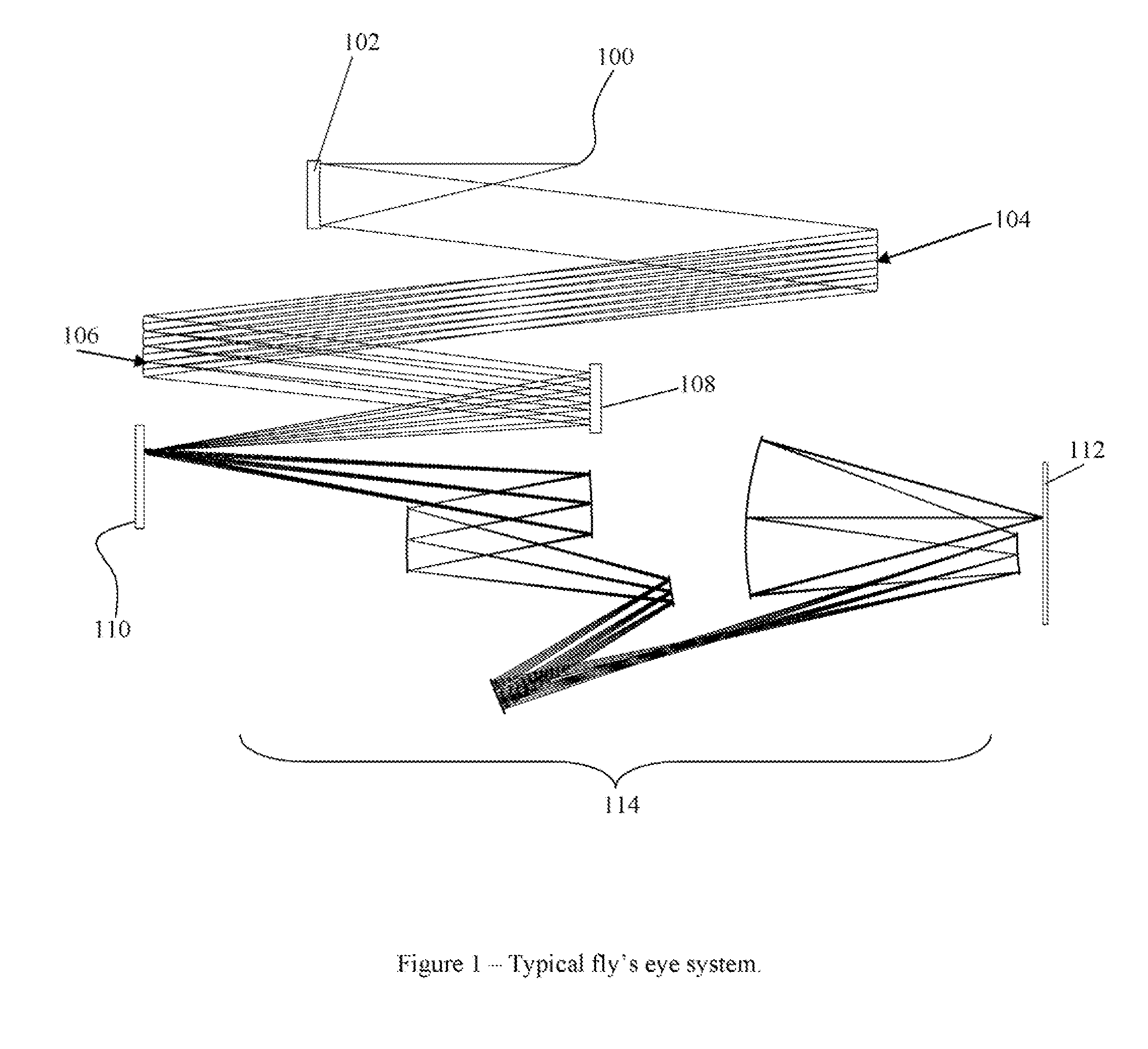
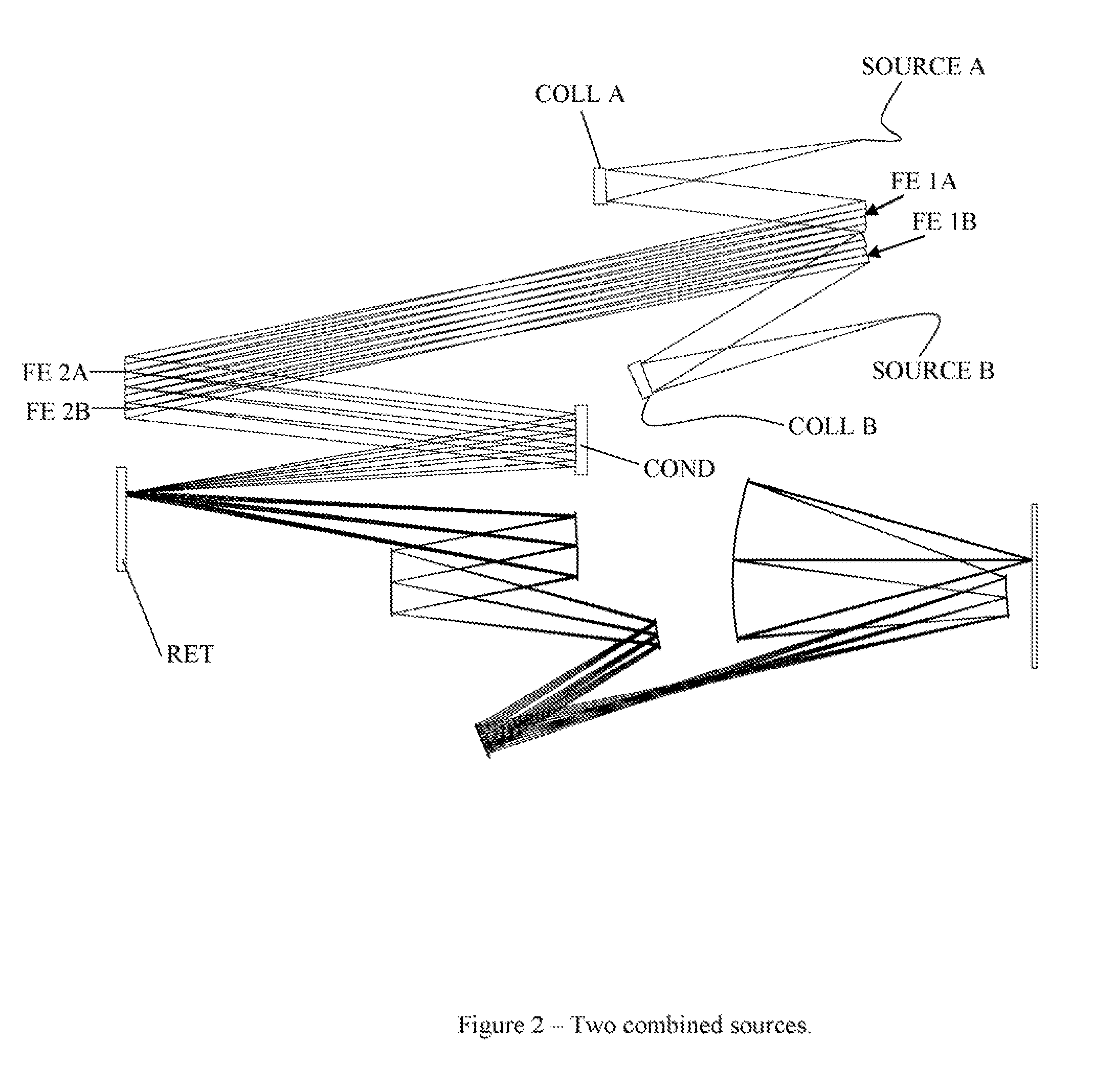
[0012]As described above, the present invention provides an illumination structure and method for EUV illumination of a reticle. The structure and method of the present invention described herein utilize known types of EUV wavelength source(s) that produce EUV radiation in a vacuum environment, and structure and method of the present invention is designed to utilize the EUV wavelength sources to illuminate a reticle. The EUV sources may be e.g. of a laser produced plasma (LPP) or discharge produced plasma (DPP) type, both of which are known to those in the art. Because the LPP source is smaller, it is contemplated that the principles of the present invention are more likely to be utilized with an LPP as the EUV source.

[0013]In this application, the term “reticle” is intended to encompass a component with a pattern that is illuminated as it is imaged to a substrate, including a refractive component as well as a reflective component, as will be recognized by those in the art.

[0014]In ...


PUM


Abstract

An apparatus and method is provided, for combining two or more EUV (extreme ultra violet) sources for illumination of a reticle. According to the principles of the present invention two or more EUV sources are combined in a single illumination system, using multiple first mirror arrays, each of which is associated with a respective EUV source, and a single second mirror array defining a pupil, and configured to receive reflected EUV radiation from the plurality of first mirror arrays, and to illuminate the reticle. Preferably, the first mirror array associated with each EUV source has a fly's eye configuration, the single second mirror array has a fly's eye configuration, and a condenser is positioned between the single second mirror array and the reticle. The number of mirror elements in the second mirror array is equal to or greater than the total number of mirror elements in the first mirror array.

Description

RELATED APPLICATION / CLAIM OF PRIORITY[0001]This application is related to and claims priority from U.S. provisional application Ser. No. 61 / 122,664, filed Dec. 15, 2008, which provisional application is incorporated by reference herein.BACKGROUND[0002]The present invention relates to illumination in an extreme ultraviolet (EUV) imaging system, and particularly to an illumination concept for increasing EUV illumination power for an EUV application such as EUV lithography.[0003]EUV lithography is an emerging technology that is designed to shrink the size of features that can be printed (imaged) by an imaging system, using illumination in the EUV (11-14 nm) wavelength range. In an EUV lithography imaging system, an EUV source (e.g. from a laser produced plasma, known in the art as LPP, or a discharge produced plasma, known in the art as DPP) is generally produced in a vacuum environment, and illuminates a reticle that is then imaged to a photo resist via a projection system that compri...

Claims


Application Information

Patent Timeline
IPC IPC(8): G02B5/08
CPCG02B13/143G02B17/0663G03F7/70033G03F7/70558G03F7/70075G03F7/70208G03F7/7005
Inventor SMITH, DANIEL G.
Owner NIKON CORP
Why Eureka
Try Eureka