
Air-based cooling for data center rack

a data center rack and air-based cooling technology, applied in the direction of domestic cooling devices, lighting and heating devices, couplings, etc., can solve the problem of reducing the likelihood of damage to electrical components, and achieve the effect of reducing heat discharge and improving the flow of chilled air

Active Publication Date: 2010-06-17
ZONIT STRUCTURED SOLUTIONS LLC
View PDF40 Cites 69 Cited by
  • Summary
  • Abstract
  • Description
  • Claims
  • Application Information

AI Technical Summary

Benefits of technology

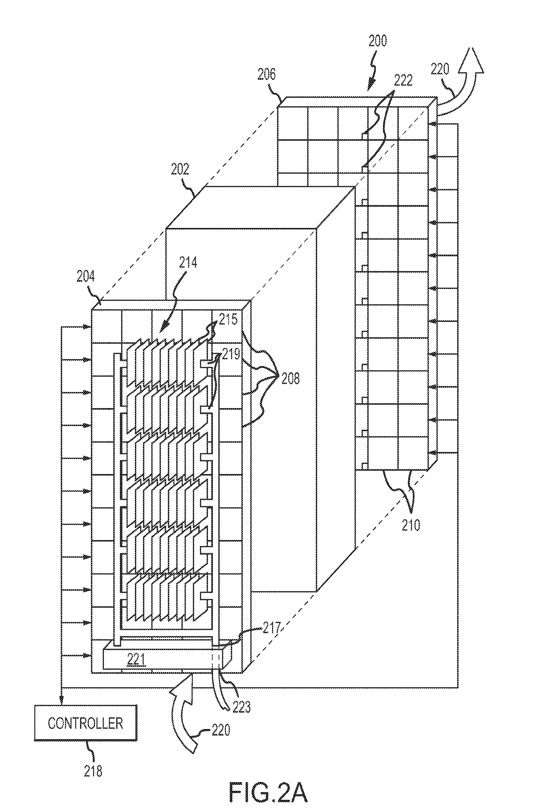
[0006]The present invention is directed to a cooling system, especially for rack-mounted electrical equipment, that uses air as a coolant fluid. The system reduces the likelihood of damage to electrical components due to any leakage of the coolant fluid. In addition, novel conduits and connectors are provided for the cooling system that enables the system to be easily reconfigured as may be desired to accommodate data center configuration and reconfiguration. Similarly, cooling system capacity can be easily increased and decreased by adding or removing modular cooling units. Moreover, in one implementation, the system includes chiller units that can be embodied as replacement doors for equipment racks so as to create and direct chilled air to potential equipment hotspots.
[0007]In accordance with one aspect of the present invention, air is used as a cooling fluid in a system for cooling electronic equipment. The associated method and apparatus (“utility”) involves providing a closed-loop coolant circuit and flowing air through the closed-loop coolant circuit such that the air functions as a coolant fluid. In this regard, the air used as the coolant fluid can be chilled, e.g., to about −40° F. or about −40° C., for example, by heat exchange with a separate coolant loop safely separated from the electronic equipment. Heat is then exchanged between the closed loop coolant circuit and ambient air so as to cool the ambient air, The cooled ambient air can then be flowed across a heat transfer surface of the electronic equipment to extract heat from the electronic equipment. As noted above, the use of air as a coolant fluid in this regard significantly reduces or substantially eliminates the possibility of damage to electronic equipment due to any leakage of the coolant fluid. The air can be at a relatively low pressure which simplifies construction, reduces maintenance and enhances reliability. In order to provide sufficient cooling in such cases, the air may be circulated at a high velocity. Each of these related aspects (low pressure and high velocity) is novel in its own right.
[0008]In accordance with another aspect of the present invention, a utility for cooling electronic equipment utilizes low-pressure air as a closed-loop coolant. Specifically, the utility involves providing a closed-loop coolant circuit, using air as the coolant in the closed-loop coolant circuit and operating the closed-loop coolant circuit at a pressure of no more than about 100 psi. In one implementation, the pressure of the coolant fluid is no more than about 48 psi. The system allows for simple construction and reconfiguration with reduced maintenance costs in relation to certain existing cooling systems. In a preferred implementation, a high velocity, low pressure (HVLP) air based cooling system is provided by combining the high velocity and low pressure aspects described above.

Problems solved by technology

The system reduces the likelihood of damage to electrical components due to any leakage of the coolant fluid.

Method used


Image

  • Air-based cooling for data center rack
  • Air-based cooling for data center rack
  • Air-based cooling for data center rack

Examples


Embodiment Construction

[0028]In the following description, the invention is set forth in the context of an air-based cooling system for data center applications. As discussed above, this is a particularly advantageous application of the present invention due to, among other things, the crowded cabling environment in such contexts, the presence of a number of hotspots and different cooling requirements for different equipment within such environments, the hazards or difficulties associated with water or other fluid coolants in such environments, and the need for flexibility in configuring and reconfiguring equipment in such environments. Nonetheless, it will be appreciated that various aspects of the invention are applicable in other contexts including other environments involving electronic equipment. Accordingly, the following description should be understood as exemplifying the invention and not by way of limitation.

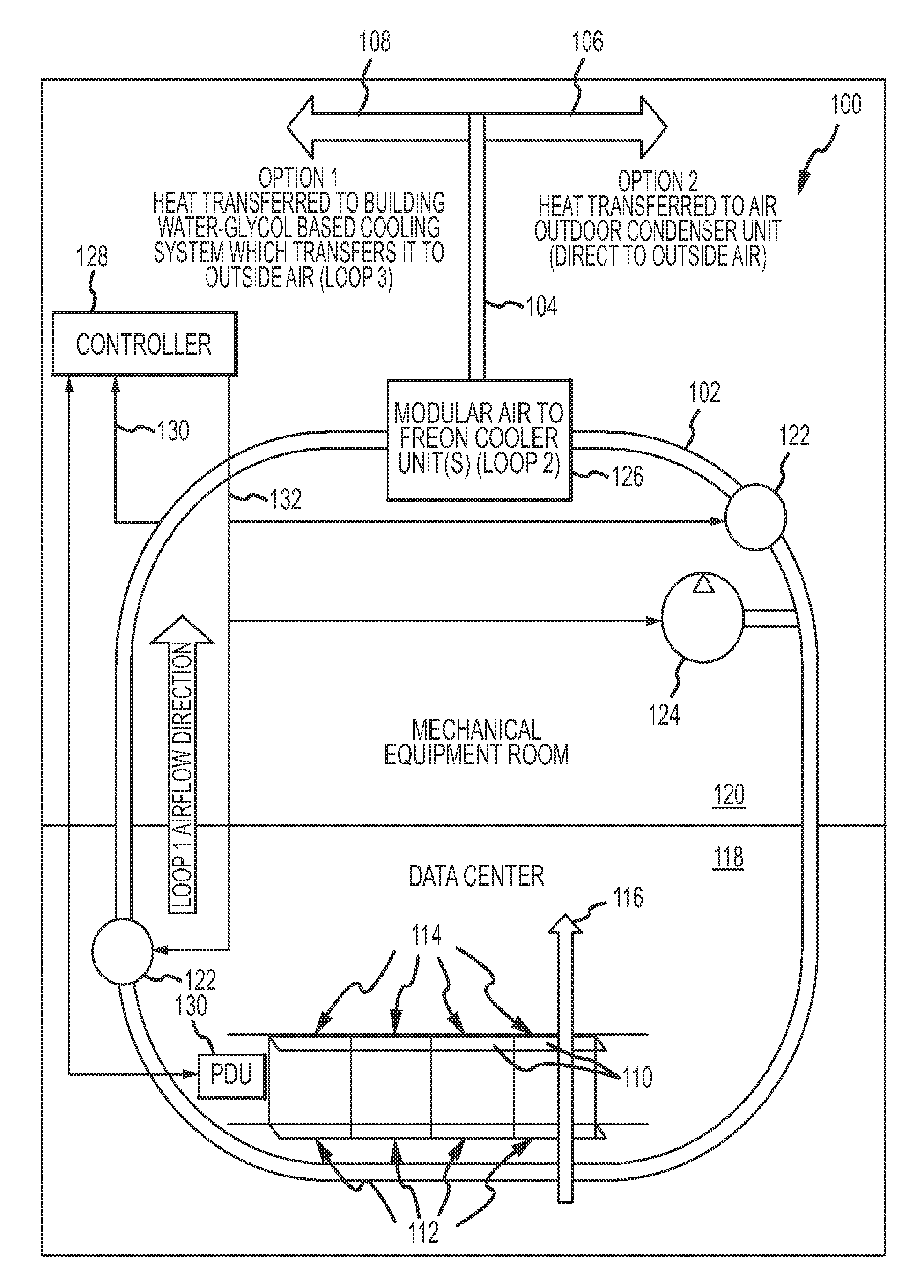
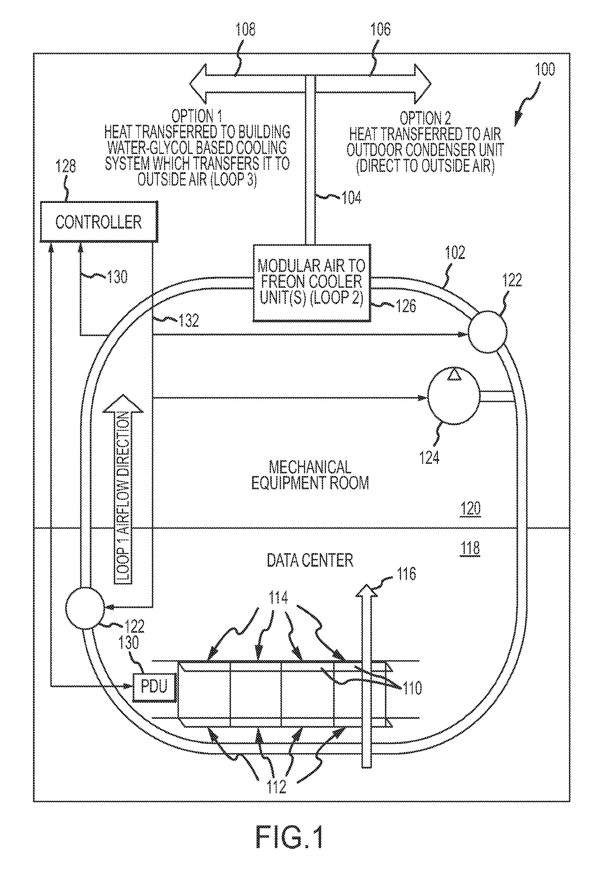
[0029]Referring to FIG. 1, a high-velocity low-pressure (IIVLP) cooling system 100 in ac...


PUM


Abstract

A high-velocity low-pressure cooling system (100), especially suited for data center applications, includes an air coolant loop (102), a non-air coolant loop (104) and a cooler unit (126) for heat transfer between the loops (102 and 104). The air loop (102) is used to chill ambient air that is blown across heat transfer surfaces of equipment mounted in data center racks (110). In this manner, effective cooling is provided using a coolant that is benign in data center environments.

Description

CROSS-REFERENCE TO RELATED APPLICATION[0001]This application claims priority under 35 U.S.C. 119 to U.S. Provisional Application No. 60 / 894,844, entitled, “AIR-BASED COOLING FOR DATA CENTER RACK,” filed on Mar. 14, 2007, the contents of which are incorporated herein as if set forth in full.FIELD OF INVENTION[0002]The present invention s generally directed to cooling electronic equipment and, in particular, to a cooling system for electrical equipment that uses air as a coolant fluid. The invention has particular utility in the context of cooling rack-mounted electrical equipment such as in a data center.BACKGROUND OF THE INVENTION[0003]Certain types of electronic equipment generate considerable heat during operation. Cooling such equipment can be problematic, particularly when a number of devices are crowded together in a compact space. The case of data centers is illustrative. Certain types of data processing equipment produce a large amount of heat in a small form factor. For exam...

Claims


Application Information

Patent Timeline
Patent Type & Authority Applications(United States)
IPC IPC(8): H05K7/20F28D15/00
CPCH05K7/20745F28D7/10H05K7/20836F16L37/46F16L37/38F16K11/0785F16L9/19
Inventor CHAPEL, STEVEPACHOUD, WILLIAM
Owner ZONIT STRUCTURED SOLUTIONS LLC
Learn More