Signal transceiver apparatus and system

a signal transceiver and wire technology, applied in the direction of digital transmission, duplex signal operation, pulse technique, etc., can solve the problems of intangible increase of area and cost of the circuit, the inability to manufacture electronic products with powerful functions, and the impedance mismatch of signal transmission between different functional circuits. achieve the effect of effectively lowering the effect of noise, easy control of wire impedance, and increasing the common mode rejection ratio

Active Publication Date: 2010-06-17
IND TECH RES INST
View PDF23 Cites 11 Cited by
  • Summary
  • Abstract
  • Description
  • Claims
  • Application Information

AI Technical Summary

Benefits of technology

[0013]Since the present invention adopts current modes to tune impedance matching, it may be applied to using various sorts of wires having different impedance to transceive signals. In other words, when the present invention is applied to transceive the signal in the chip, a problem of not easily controlling the impedance accurately in the wire is overcome. Moreover, the present inven...

Problems solved by technology

In recent years, due to advances in technology of semiconductor fabrication, manufacturing electronic products that are light, thin, small and having powerful functions has become a main issue in product designs of the modern electronic products.
However, no matter using what sort of the abo...

Method used


Image

  • Signal transceiver apparatus and system
  • Signal transceiver apparatus and system
  • Signal transceiver apparatus and system

Examples


Embodiment Construction

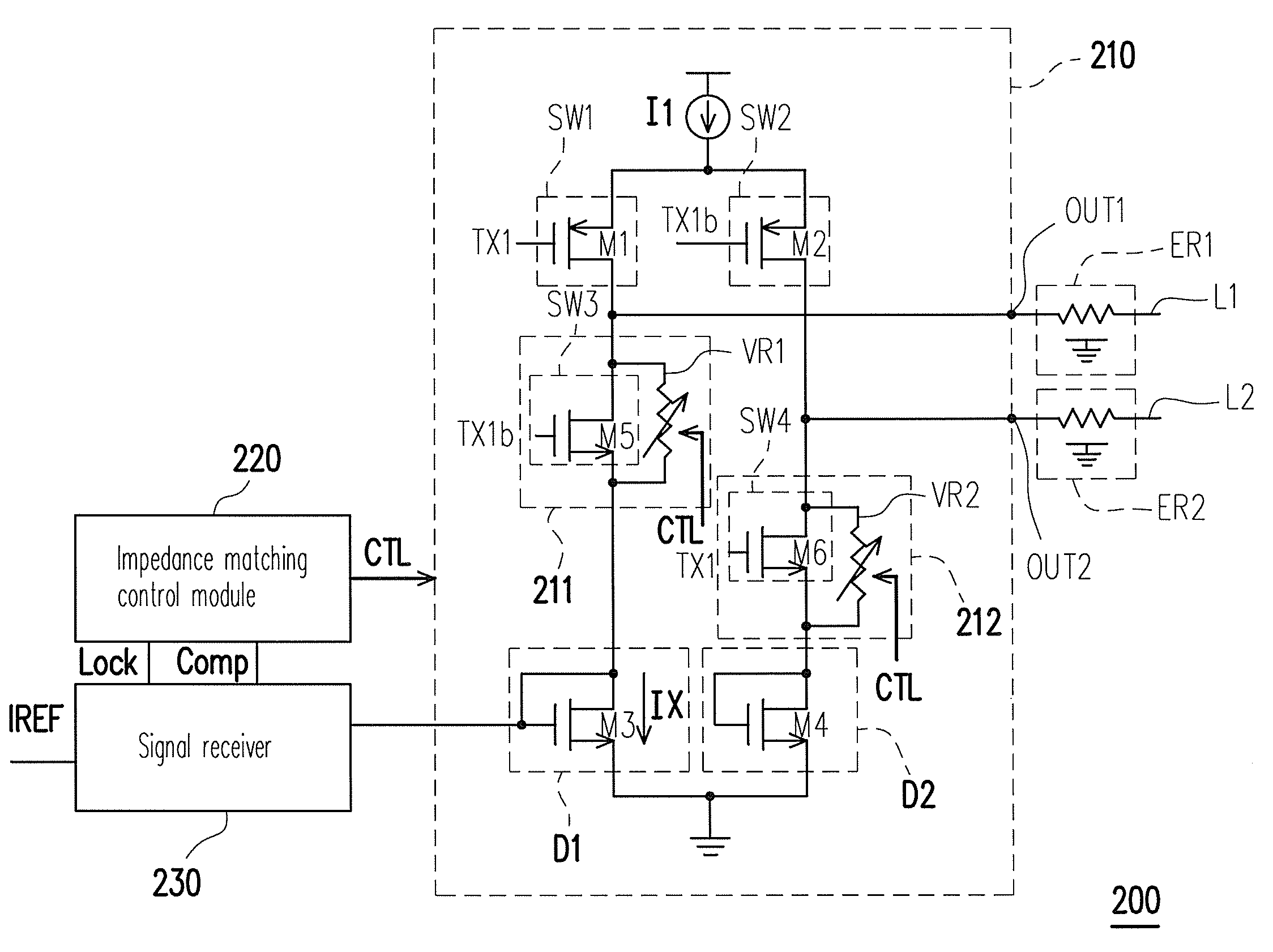
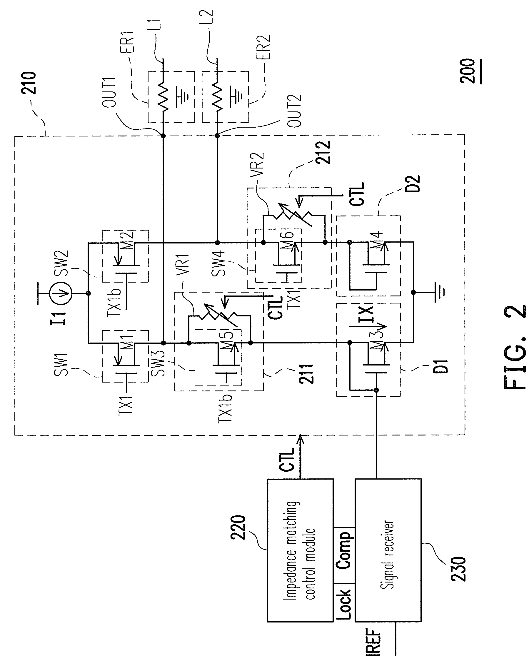
[0027]The following provides a plurality of embodiments of a signal transceiver apparatus of the present invention for illustration, and figures are accompanied in hope that persons having ordinary skills in the art have a better understanding and are capable of implementation.

[0028]First referring to FIG. 2, which is a schematic diagram showing a signal transceiver apparatus according to an embodiment of the present invention. A signal transceiver apparatus 200 includes a signal transmitter 210, an impedance matching control module 220 and a signal receiver 230. According to the present embodiment, the signal transmitter 210 includes an output end OUT1 and an inverse output end OUT2. The output end OUT1 and the inverse output end OUT2 are respectively connected to transceiver wires L1 and L2. The transceiver wire L1 has equivalent impedance ER1 and the transceiver wire L2 has an equivalent impedance ER2. Moreover, the signal transmitter 210 includes impedance tuners 211 and 212. Th...


PUM


Abstract

A signal transceiver apparatus suitable for a wired signal transceiver system includes a differential signal transmitter, an impendence matching control module and a signal receiver. The signal transmitter has an output terminal which is connected to a transceiver wire. The signal transmitter includes a first impendence tuner and is used to receive a control signal so as to tune impendence of the first impendence tuner according to the control signal. Moreover, the impendence matching control module generates the control signal according to a compare signal and a lock signal. Besides, the signal receiver generates the lock signal and the compare signal according to a compare result between a current flowing through the first impendence tuner and a reference current.

Description

CROSS-REFERENCE TO RELATED APPLICATION[0001]This application claims the priority benefit of Taiwan application serial no. 97149284, filed on Dec. 17, 2008. The entirety of the above-mentioned patent application is hereby incorporated by reference herein and made a part of specification.BACKGROUND OF THE INVENTION[0002]1. Field of the Invention[0003]The present invention relates to a signal transceiver apparatus and system, and particularly to a wired signal transceiver apparatus and system.[0004]2. Description of Related Art[0005]In recent years, due to advances in technology of semiconductor fabrication, manufacturing electronic products that are light, thin, small and having powerful functions has become a main issue in product designs of the modern electronic products. Regarding requirements in such aspects, engineers often use technologies that dispose a great number of circuits on a single chip and methods of so-called system on chip (SOC) to cope.[0006]However, no matter using...

Claims


Application Information

Patent Timeline
IPC IPC(8): H04L5/16
CPCH04L25/0276H04L25/0282H04L25/0278
Inventor HUANG, HONG-YIPU, RUEI-IUNCHU, YUAN-HUA
Owner IND TECH RES INST
Why Eureka
Try Eureka