Upper internals arrangement for a pressurized water reactor

a pressurized water reactor and internal arrangement technology, applied in nuclear reactors, nuclear elements, greenhouse gas reduction, etc., can solve the problems of no support for the instrumentation above, significant repair problems, etc., and achieve the effect of reducing the additional disassembly requirements

Active Publication Date: 2010-06-17
WESTINGHOUSE ELECTRIC CORP
View PDF8 Cites 33 Cited by
  • Summary
  • Abstract
  • Description
  • Claims
  • Application Information

AI Technical Summary

Benefits of technology

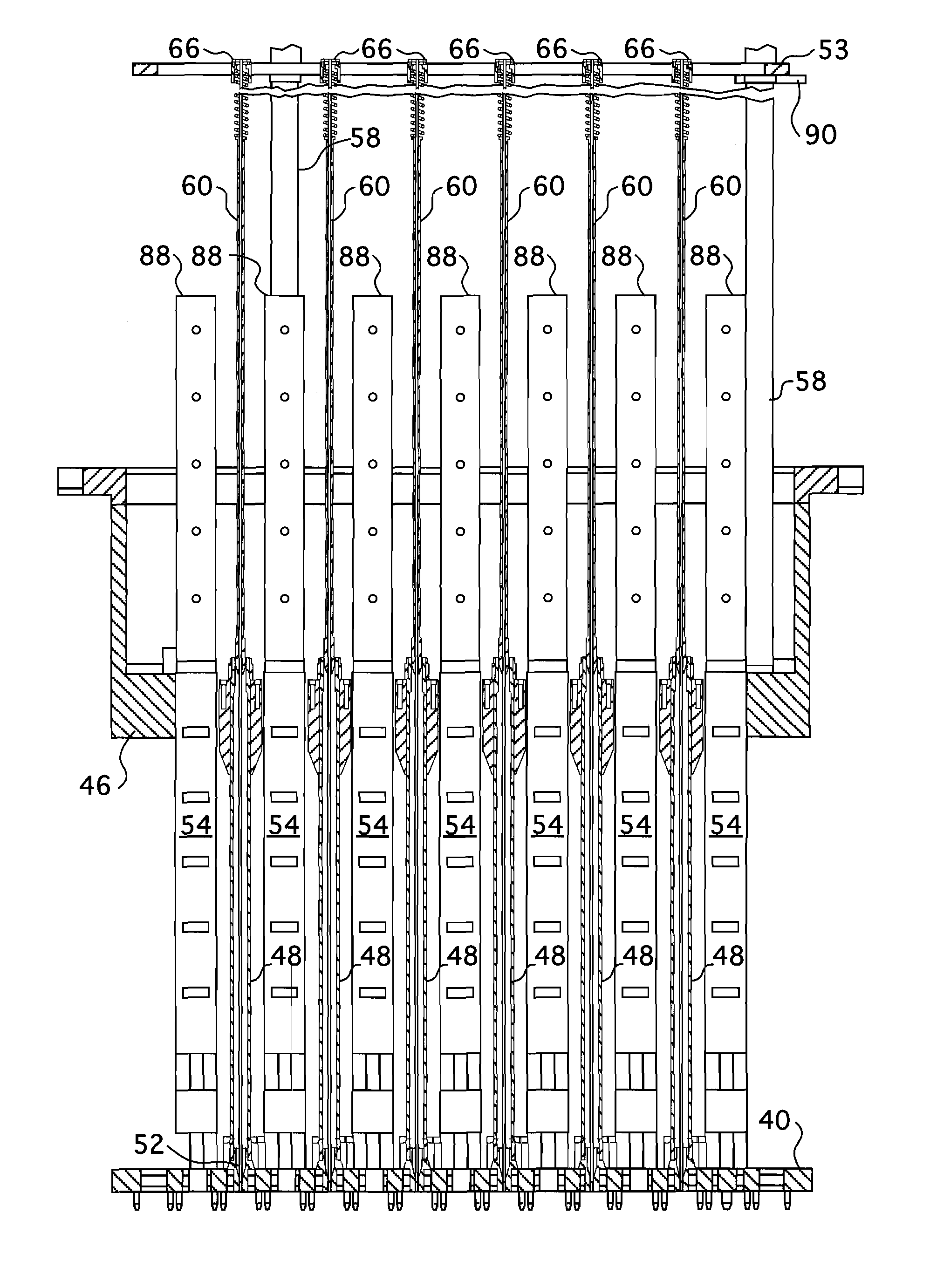
[0007]This invention provides support for the in-core instrumentation above the upper support plate when the in-core instrumentation is withdrawn from the core. The design of this invention provides a support system for the upper internals in-core instrumentation. Furthermore, the design of this invention minimizes additional disassembly requirements to remove and install the upper internals guide tubes in the event maintenance of the guide tubes is required.
[0010]In one preferred embodiment, the slidable sleeves comprise a plurality of concentric telescoping tubes that extend between the instrumentation grid assembly and the corresponding support column. Preferably, a spiral spring extends around an inner most one of the concentric telescoping tubes below an attachment of the slidable sleeve to the instrumentation grid assembly between the attachment of the slidable sleeve to the instrumentation grid assembly and another of the telescoping tubes. The spring provides a holddown force on the telescoping tubes when the instrumentation grid assembly is in a lower most position, to prevent vibration during reactor operation. Desirably, one end of the spring extends at least partially into the opening in the instrumentation grid assembly through which the slidable sleeve extends and another end of the spring extends axially below the opening in the instrumentation grid assembly. The lower end of the spring is preferably surrounded by a can housing that is slidably mounted within the instrumentation grid assembly opening. Desirably, an upper portion of the can housing is captured within the opening of the instrumentation grid assembly to restrain the spring between the instrumentation grid assembly opening and the bottom of the can housing.

Problems solved by technology

In a few instances in the past, leakage occurred at the penetrations at the bottom of the vessel which presented significant repair problems.
However, even the fixed in-core neutron detectors have to be withdrawn from the fuel assemblies before the reactor core can be accessed for refueling operations.
However, presently there is no support for the instrumentation above the upper support plate assembly through which the in-core instrumentation has to be withdrawn to clear the bottom of the upper core plate.

Method used


Image

  • Upper internals arrangement for a pressurized water reactor
  • Upper internals arrangement for a pressurized water reactor
  • Upper internals arrangement for a pressurized water reactor

Examples


Embodiment Construction

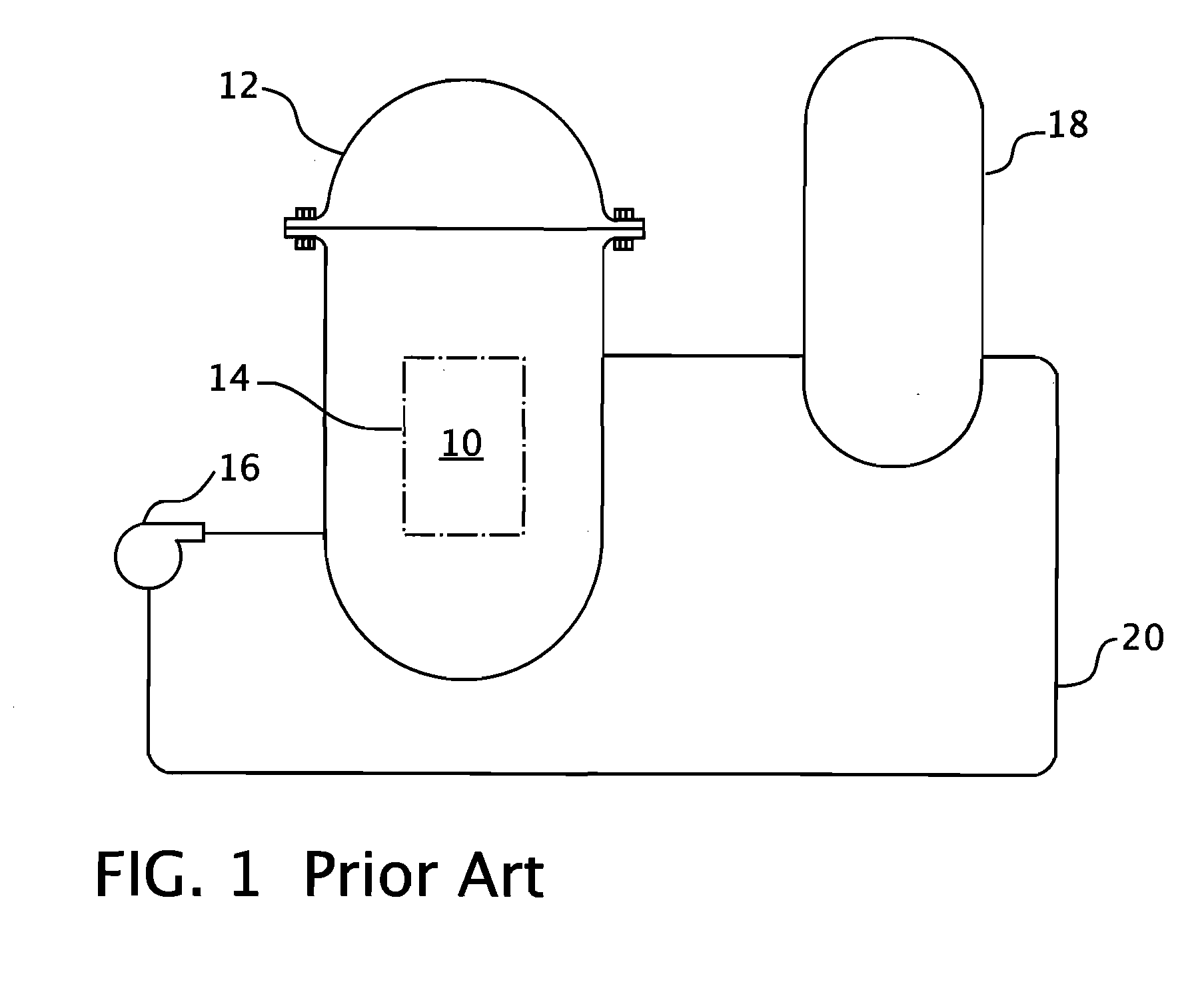
[0025]Referring now to the drawings, FIG. 1 shows a simplified nuclear reactor primary system, including a generally cylindrical pressure vessel 10 having a closure head 12 enclosing a nuclear core 14. A liquid reactor coolant, such as water, is pumped into the vessel 10 by pump 16 through the core 14 where heat energy is absorbed and is discharged to a heat exchanger 18, typically referred to as a steam generator, in which heat is transferred to a utilization circuit (not shown) such as a steam driven turbine generator. The reactor coolant is then returned through pump 16, completing the primary loop. Typically, a plurality of the above described loops are connected to a sealed reactor vessel 10 by reactor coolant piping 20.

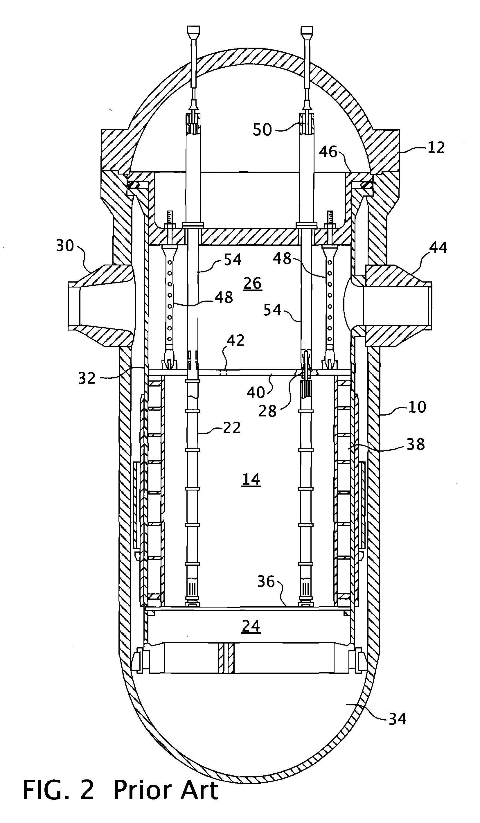
[0026]A conventional reactor design is shown in more detail in FIG. 2. As previously mentioned, though not shown in FIG. 2, in a conventional pressurized water reactor design, the movable in-core neutron detectors enter the core from the bottom of the reactor th...


PUM


Abstract

A telescoping guide for extraction and reinsertion support handling of in-core instrument thimble assemblies in the area above the upper support plate in the upper internals of a pressurized water reactor. The telescoping guides extend between the upper ends of the upper internals support columns and an axially movable instrumentation grid assembly which is operable to simultaneously raise the telescoping guides and extract the in-core instrument thimble assemblies from the reactor fuel assemblies.

Description

CROSS REFERENCE TO RELATED APPLICATION[0001]This application claims priority to provisional patent application Ser. No. 61 / 138,155 filed Dec. 17, 2008.BACKGROUND OF THE INVENTION[0002]1. Field of the Invention[0003]This invention relates to water cooled nuclear reactors, and more particularly, to pressurized water reactors having in-core instrumentation (in-core instrument thimble assemblies) that enter the reactor vessel through penetrations from the top of the reactor vessel and are used to monitor the neutron activities and coolant temperature within the core fuel assemblies.[0004]2. Description of Related Art[0005]Many water cooled nuclear reactors utilize a core of vertically positioned fuel assemblies within a reactor vessel. To monitor the neutron activities and coolant temperature within the core fuel assemblies, movable in-core instrumentation, such as movable neutrons detectors, conventionally enter the core from penetrations in the bottom of the vessel. In a few instances...

Claims


Application Information

Patent Timeline
Patent Type & Authority Applications(United States)
IPC IPC(8): G21C1/08G21C17/00G21C19/00
CPCG21C13/02G21C17/10Y02E30/40G21C19/02G21C17/116Y02E30/30
Inventor WEISEL, ERIC M.MARGOTTA, KENNETH V.WALUS, DANIELSCHILDKAMP, THOMAS J.HAHN, JOSEPH J.HEIBEL, MICHAEL D.
Owner WESTINGHOUSE ELECTRIC CORP
Why Eureka
Try Eureka