Noise control device

a technology of noise control and noise reduction, which is applied in the direction of noise generation, ear treatment, instruments, etc., can solve the problems of deteriorating noise reduction effect, achieve the effect of preventing an increase in input/output delay, noise reduction effect, and reducing nois

Active Publication Date: 2010-06-17
PANASONIC CORP
View PDF7 Cites 98 Cited by
  • Summary
  • Abstract
  • Description
  • Claims
  • Application Information

AI Technical Summary

Benefits of technology

[0037]According to the above first aspect, a noise reduction control is performed for the plurality of spaces which are acoustically independent from each other, by using a common cancellation signal generated by the single first signal generation means. In other words, according to this aspect, the single first signal generation means is used in common for the plurality of acoustically independent spaces. Here, the noises respectively arriving in the plurality of acoustically independent spaces are highly correlated to each other in a low frequency band. For this reason, when the single first signal generation means is used in common for the plurality of acoustically independent spaces, the noises respectively arriving in the plurality of acoustically independent spaces can be sufficiently reduced. As a result, according to this aspect, the number of first signal generation means each of which performs a large amount of processing can be reduced to 1, while sufficiently producing the noise reduction effect. Consequently, according to this aspect, a noise control device, which is capable of preventing an increase in an input / output delay at the first signal generation means even in the case where the processing at the first signal generation means is performed by a single arithmetic processing circuit, can be provided.
[0038]According to the above second aspect, an increase in the noise, which the user may feel due to the cancellation sound having a low correlation in other frequency bands than the low frequency band, can be avoided without newly providing a control circuit.
[0039]According to the above third aspect, the noise reduction effect can be further enhanced.
[0040]According to the above fourth aspect, since the first and second signal generation means respectively generate cancellation signals having different frequency bands from each other, processing loads on the first and second signal processing means can be reduced.
[0041]According to the above fifth aspect, an optimal control can be performed in accordance with the phase lag of the electroacoustic transfer function. This allows a frequency band, in which the noise reduction effect is obtained, to be further widened.
[0042]According to the above sixth to eighth aspects, an optimal noise reduction effect can be produced in accordance with an arrival direction of the noise.

Problems solved by technology

For this reason, there is a problem that even if, e.g., the transfer function CL is set to have an inverse characteristic to that of the electroacoustic transfer function HL, the transfer function CL does not have the inverse characteristic to that of the electroacoustic transfer function HL in the radio frequency band, whereby noise reduction effect deteriorates.

Method used


Image

  • Noise control device
  • Noise control device
  • Noise control device

Examples


first embodiment

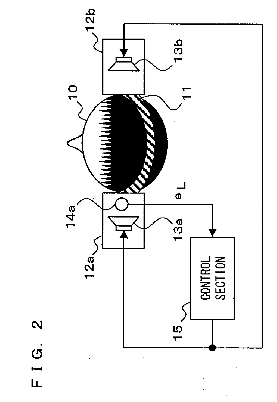
[0103]Hereinafter, a noise control device according to a first embodiment of the present invention will be described with reference to the drawings. First, a configuration of the noise control device according to the present embodiment will be described with reference to FIG. 2. FIG. 2 shows the configuration of the noise control device according to the first embodiment. Note that, FIG. 2 shows a configuration in the case where the noise control device according to the present embodiment is applied in a headphone apparatus. FIG. 2 and later-described FIGS. 3, 7 and 8 each are a diagram which shows a view seen from above a head of a user 10 and in which the user 10 faces upward.

[0104]As shown in FIG. 2, the noise control device comprises a headband 11, a left ear case 12a, a right ear case 12b, a left ear speaker 13a, a right ear speaker 13b, a left ear microphone 14a and a control section 15. The left ear case 12a is placed near a left ear of the user 10, and the left ear case 12a h...

second embodiment

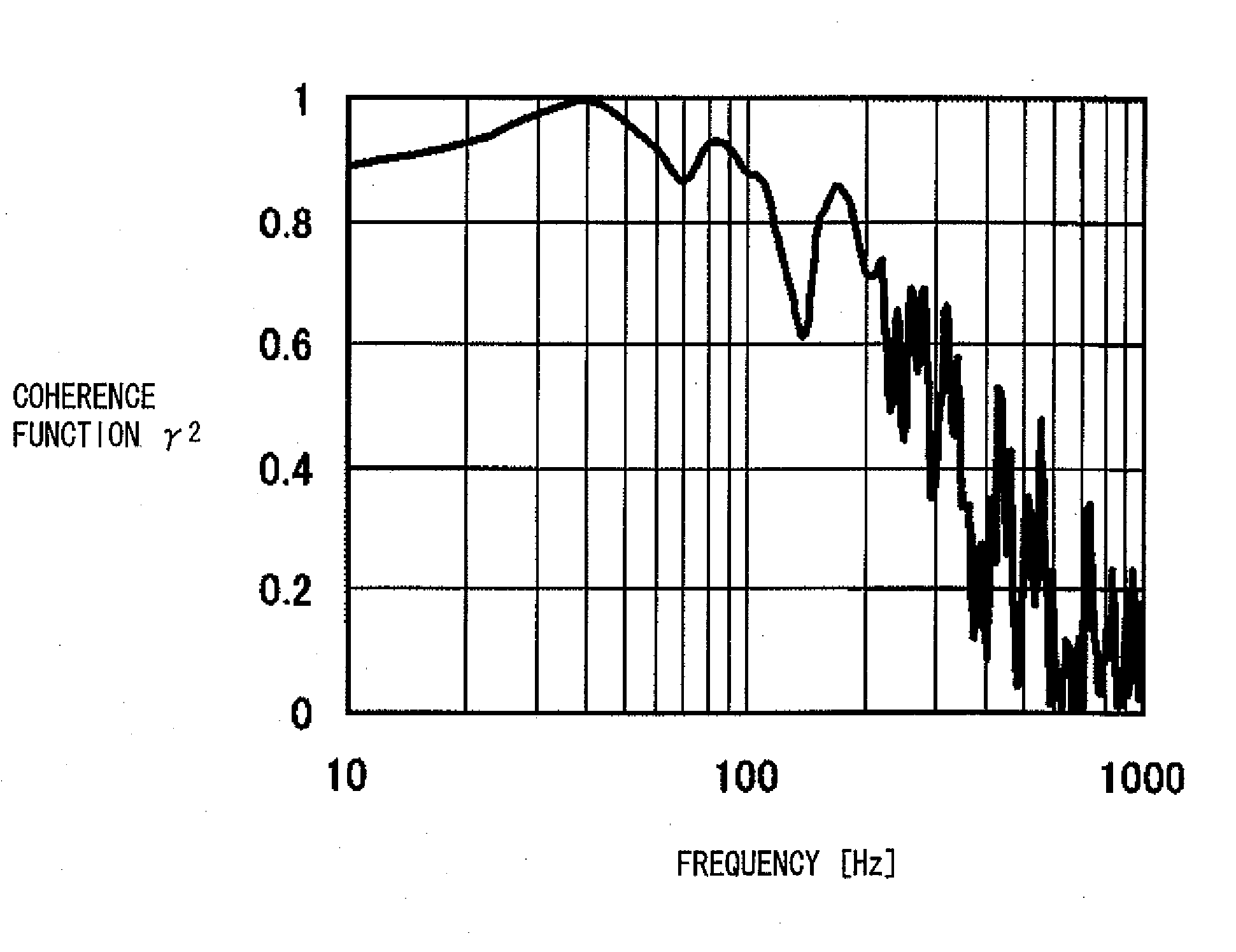
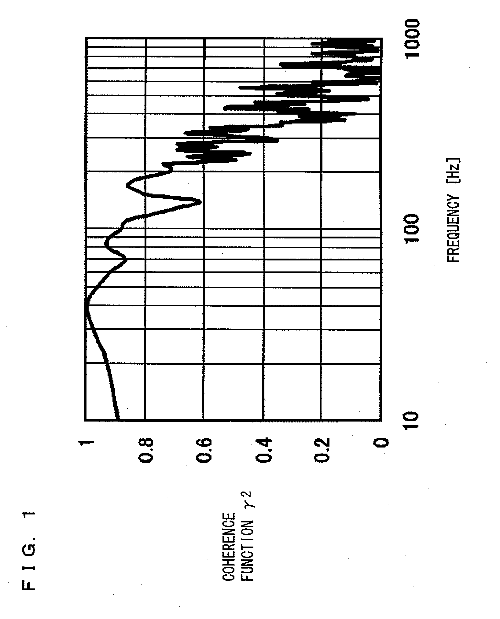
[0137]Hereinafter, a noise control device according to a second embodiment of the present invention will be described with reference to the drawings. Usually, in a high frequency band, a phase lag of each of the aforementioned electroacoustic transfer functions HL and HR occurs. Accordingly, there is a case where even if the transfer function CL of the control section 15 described in the first embodiment is set so as to have the inverse characteristic to that of the electroacoustic transfer function HL, the transfer function CL does not have the inverse characteristic in a high frequency band, whereby the noise reduction effect decreases. For this reason, in the present invention, for a frequency band which is higher than a predetermined frequency and in which a phase lag of the electroacoustic transfer function occurs, a control is separately performed by using a high frequency control section for which a filter coefficient based on the electroacoustic transfer function having the ...

third embodiment

[0148]Hereinafter, the noise control device according to a third embodiment of the present invention will be described with reference to the drawings. The noise control device according to the present embodiment is, as compared to the above second embodiment, further capable of producing an optimal noise reduction effect in accordance with an arrival direction of noise.

[0149]A configuration of the noise control device according to the third embodiment will be described with reference to FIG. 12. FIG. 12 shows a configuration of the noise control device according to the third embodiment. As shown in FIG. 12, the noise control device comprises the headband 11, the left ear case 12a, the right ear case 12b, the left ear speaker 13a, the right ear speaker 13b, the left ear microphone 14a, the right ear microphone 14b, the control section 15a, the adders 21a and 21b, the left ear high frequency control section 25a, the right ear high frequency control section 25b, and a switching section...


PUM


Abstract

A noise control device according to the present invention is capable of reducing noises respectively arriving in a plurality of spaces which are acoustically independent from each other. The noise control device comprises: sound output means, which are respectively provided in the plurality of spaces so as to respectively correspond to the plurality of spaces, each for outputting a sound to a corresponding space; noise detection means, which is provided in at least one of the plurality of spaces, for detecting a noise arriving in the at least one of the plurality of spaces; and signal generation means which is a single means for generating, based on the noise detected by one of the noise detection means, a cancellation signal for canceling the noise, and outputting the generated cancellation signal to each of the plurality of sound output means.

Description

TECHNICAL FIELD[0001]The present invention relates to a noise control device, and particularly to a noise control device for reducing noises respectively arriving in a plurality of spaces which are acoustically independent from each other.BACKGROUND ART[0002]In recent years, a so-called noise-canceling headphone is in the market in response to the growing needs of improvement in comfortability in an environment where there is too much noise, typically an aircraft cabin or the like, which noise-canceling headphone is a headphone apparatus using an active noise control technique in which a control sound in antiphase to a noise is actively outputted, whereby the noise is reduced (e.g., Patent Document 1).[0003]Hereinafter, a conventional noise-canceling headphone will be described with reference to FIG. 20. FIG. 20 shows a configuration of the conventional noise-canceling headphone. Here, FIG. 20 shows a view seen from above a head of a user 90. In FIG. 20, the user 90 faces upward.[00...

Claims


Application Information

Patent Timeline
Patent Type & Authority Applications(United States)
IPC IPC(8): A61F11/06
CPCG10K11/1782H04R3/002H04R1/1083G10K2210/1081G10K11/17813G10K11/17823G10K11/17833G10K11/17854G10K11/17857G10K11/17881
Inventor MIZUNO, KO
Owner PANASONIC CORP
Why Eureka
Try Eureka