Image processing method and image processing apparatus
Inactive Publication Date: 2010-06-17
KONICA MINOLTA INC
View PDF4 Cites 5 Cited by
Summary
Abstract
Description
Claims
Application Information
AI Technical Summary
This helps you quickly interpret patents by identifying the three key elements:
Problems solved by technology
Method used
Benefits of technology
Benefits of technology
[0056]According to above Item 1 of the invention, there is presented an image processing method that compresses the dynamic range of image data including plural pixels. By this method, an image-processed value of each pixel is obtained from the value of the low frequency component of the each pixel calculated from inputted image data and the value of the each pixel of the inputted image data, and according to the following equation:Snp=a1Snus+a2·(Snf−Snus),wherein factors a1 and a2 are set within the range 0<a1<1 and 0<a2<1, and a monotone decreasing function of (Snf−Snus) is defined as factor a2.
[0057]Thus, the ratio between the low frequency component Snus and the high frequency component (Snf−Snus) is properly defined, and halo is reduced.
[0058]According to Item 2, in Item 1 of the invention, functions of (Snf−Snus) are defined as factor a1 and factor a2, and thus an image processing method is presented which further reduces halo.
[0059]According to Item 3, in item 2 of the invention, a monotone increasing function of (Snf−Snus) is defined as factor a1, an thus an image processing method is presented which further reduces halo.
[0060]According to Item 4, in Item 1 of the invention, an image processing method is presented which allows easy extraction of the base component and the detail component of an image.
[0061]According to Item 5 of the invention, there is presented an image processing apparatus that includes an image processing unit that compresses the dynamic range of image data including plural pixels, and a unit that obtains an image-processed value of each pixel from the value of the low frequency component of the each pixel calculated from inputted image data and the value of the each pixel of the inputted image data, and according to the following equation:Snp=a1*Snus+a2·(Snf−Snus),wherein factors a1 and a2 are set within the range 0<a1<1 and 0<a2<1, and a monotone decreasing function of (Snf−Snus) is defined as factor a2.
Problems solved by technology
However, this method has a problem, as described below, in compressing the dynamic range of an image.
Method used
Image
Click on the blue label to locate the original text in one second.
Reading with bidirectional positioning of images and text.
Examples
embodiment 1
[0096]In Embodiment 1, image processing is performed by the following equation;
Snp=a1·Snus+a2·(Snf−Snus)
representing an image processing method in accordance with the invention.
[0097]Herein,
[0098](Snf−Snus)=Snd represents the detail component,
[0099]Sndmin represents the minimum of Snd, and
[0100]Sndmax represents the maximum of Snd,
[0101]while[0102]factor a1 is defined to be a monotone increasing function of Snd:
a1=0.1·((Snd−Sndmin) / (Sndmax−Sndmin))+0.2,
and factor a2 is defined to be a monotone decreasing function of Snd:
a2=0.5·(1.0−(Snd−Sndmin) / (Sndmax−Sndmin))+0.1.
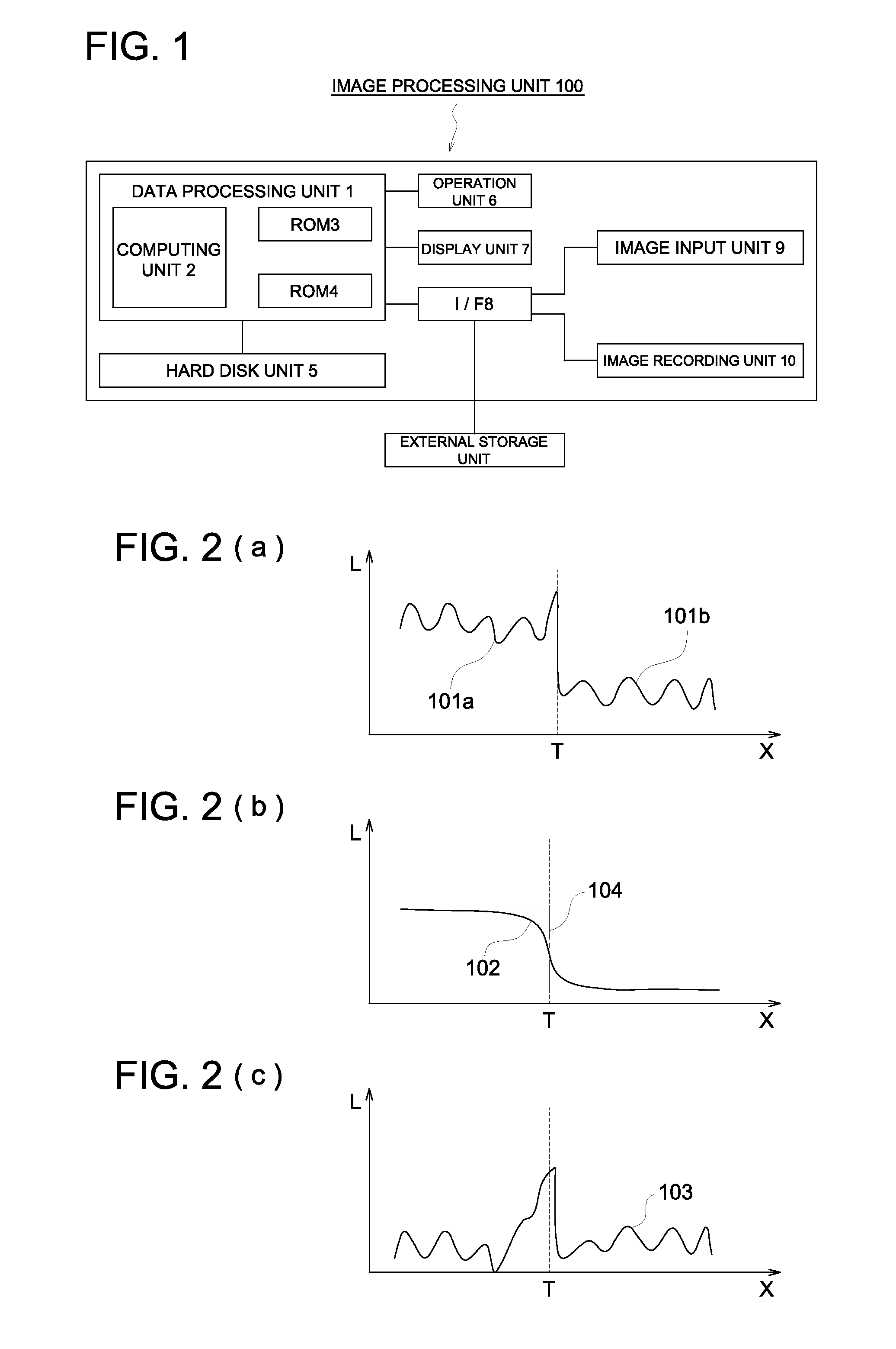
[0103]A result of image processing, described above, will be described, referring to FIGS. 7 and 8. Similarly to FIG. 2, the horizontal axis in FIG. 7 indicates positions along a line passing through the portion of which luminance varies steeply on the original image. The vertical axis in FIG. 7 indicates the values of image data indicating luminance at the respective positions thereof. Similarly to FIG. 2, in FIG. 7, T i...
embodiment 2
[0109]In Embodiment 2, image processing is performed by the equation:
Snp=a1·Snus+a2·(Snf−Snus)
[0110]representing an image processing method in accordance with the invention with factor a1=0.3 and factor a2=0.1.
[0111]A result of image processing, described above, will be described, referring to FIG. 9. Similarly to FIG. 7, the horizontal axis in FIG. 9 indicates positions along a line passing through the portion of which luminance changes steeply on the original image. The vertical axis in FIG. 9 indicates the values of image data indicating luminance at the respective positions thereof. In FIG. 9, T indicates the boundary between the light portion and the dark portion, similarly to FIG. 7, FIG. 9(a) shows a base component 131 of the original image and a base component 132 compressed by the above described image processing method. AS described above, the base component is compressed by setting the factor a1 to 0.3.
[0112]FIG. 9(b) shows a detail component 133 of the original image dat...
PUM
Abstract
To effectively remove halo in an image processing method and an image processing apparatus for compressing the dynamic range of an image to convert the image to an image suitable for image recording or image display. The means for achieving this purpose comprises, in an image processing method for compressing the dynamic range of an image, an inputting step of inputting image data; a low frequency component calculating step of calculating the low frequency component of the input image data for each pixel; an image processing step of calculating an image process value for each pixel by use of an equation indicated below; and an outputting step of outputting image data including the image process value calculated in the image processing step. Snp=a1·Snus+a2·(Snf−Snus), where Snp represents an image process value, a1 and a2 are coefficients (0<a1<1, 0<a2<1), Snus represents a low frequency component of each pixel calculated in the low frequency component calculating step, and Snf represents an image data value of each pixel inputted in the inputting step.
Description
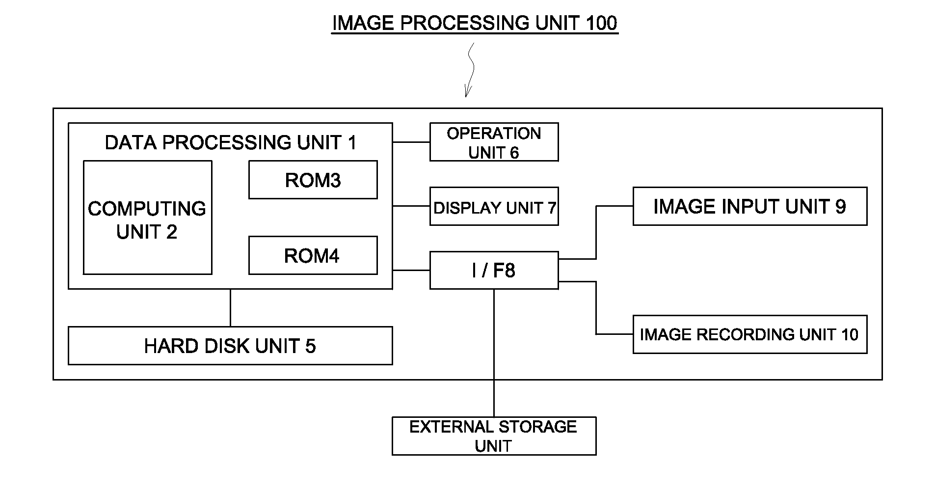
TECHNICAL FIELD[0001]The present invention relates to an image processing method and apparatus for conversion of an image into an image suitable for image recording and display by compressing the dynamic range of the image.TECHNICAL BACKGROUND[0002]In the field of color photographing and medical imaging, recent improvement in performance of computers, mass-storage of storage devices, and reduction in cost have achieved a wide use of methods that read an image as digitized image data by use of a digital camera or image reading device, store the image in a storage device and perform appropriate image processing, and thereafter record the image data as a hard copy on a film or printing paper or visualize the image on a display device.[0003]In recent years, improvement in performance of solid image pickup devices, such as CCD (Charge Coupled Device) image sensor or CMOS (Complementary Metal-OxideSemiconductor) image sensors and development of application technology of these have enable...
Claims
Application Information
Patent Timeline
Application Date:The date an application was filed.
Publication Date:The date a patent or application was officially published.
First Publication Date:The earliest publication date of a patent with the same application number.
Issue Date:Publication date of the patent grant document.
PCT Entry Date:The Entry date of PCT National Phase.
Estimated Expiry Date:The statutory expiry date of a patent right according to the Patent Law, and it is the longest term of protection that the patent right can achieve without the termination of the patent right due to other reasons(Term extension factor has been taken into account ).
Invalid Date:Actual expiry date is based on effective date or publication date of legal transaction data of invalid patent.

