
Uv-curable coatings and methods for applying uv-curable coatings using thermal micro-fluid ejection heads

Inactive Publication Date: 2010-06-17
LEXMARK INT INC
View PDF5 Cites 12 Cited by
  • Summary
  • Abstract
  • Description
  • Claims
  • Application Information

AI Technical Summary

Benefits of technology

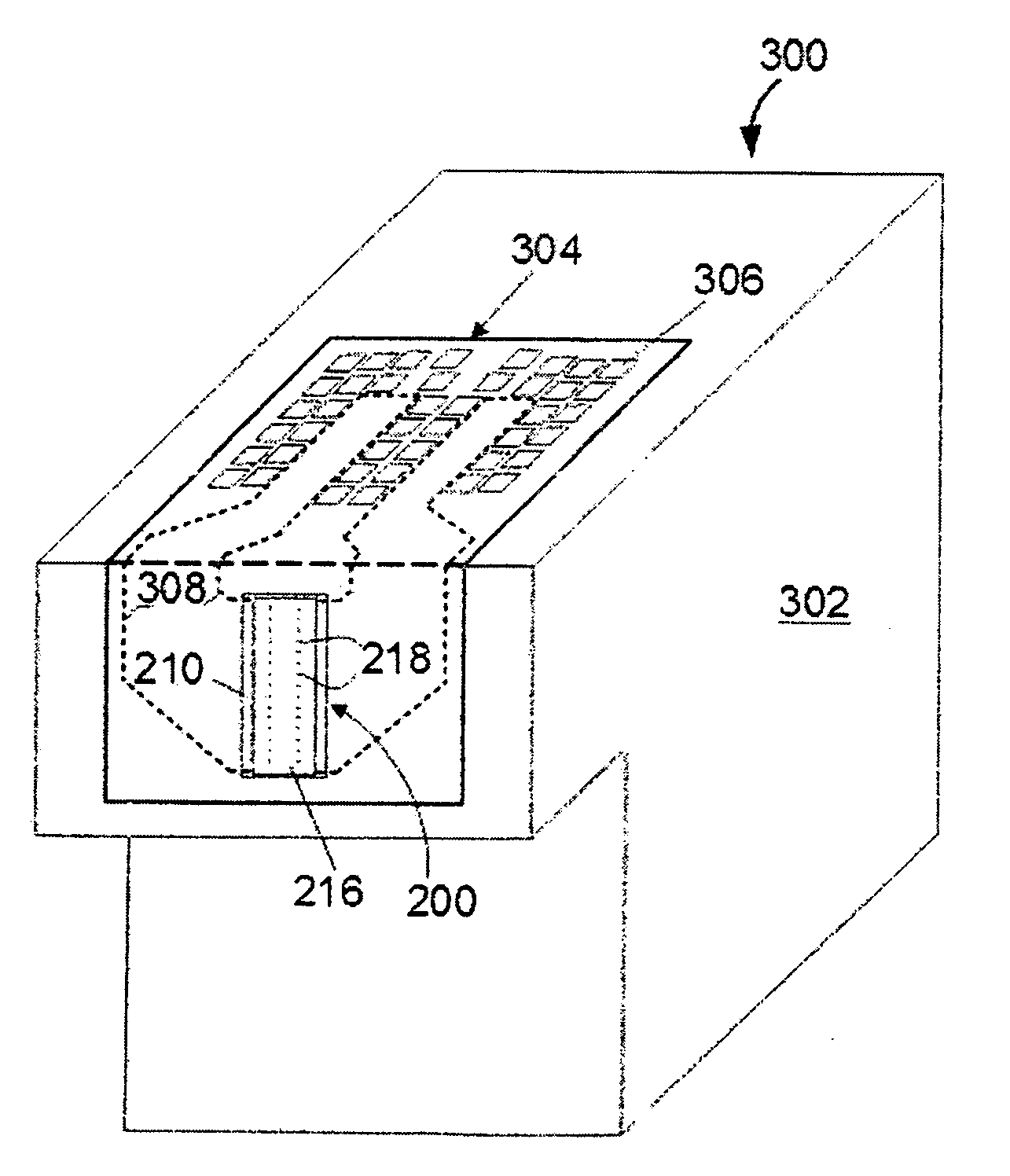
[0007]In another embodiment, there is provided a thermal micro-fluid ejection head for ejecting a UV-curable fluid onto a surface. The ejection head includes a nozzle plate having a radiation opaque coating thereon for preventing premature curing of the fluid.
[0012]An advantage of embodiments of the disclosure may be minimal nozzle plate flooding thereby greatly improving droplet ejection directionality and droplet placement on a substrate. Aqueous UV-curable fluids, as described herein, provide a fire frequency that is 40% less than a fire frequency of a conventional aqueous-based ink composition. The fire frequency is lower because the UV-curable fluids generally have higher viscosity than traditional aqueous-based inks thereby reducing the refill rate to fluid ejection chambers. In other words, the micro-fluid ejection system ejecting a UV-curable fluid is more damped than a system operating on a conventional aqueous-based ink. However, despite the lower fire frequency, the UV-curable fluid may actually have no negative impact on throughput of imaged substrates because of minimal flooding, straighter droplet directionality, better droplet placement, and fewer shingling passes needed to provide an image.

Problems solved by technology

However, UV-curable coatings and inks come with a unique set of problems that have already been solved for conventional inks and coatings.
Such piezoelectric ejection heads are generally more costly than thermal ejection heads and are typically provided separate from the ink supplies making maintenance of the ejection heads more difficult and costly.
There are several disadvantages to the use of solvent-based inks and coatings.
Secondly, solvent based inks and coatings are much more hazardous and pose more danger to the environment than aqueous-based inks and coatings.
Another problem with the use of UV-curable inks and coatings is that the fluids cure when exposed to light.
While this is desirable when the fluids are to be cured on a surface, curing of such fluids on the surfaces of the ejection devices or in the ejection nozzles may cause misfiring and other unwanted results.

Method used


Image

  • Uv-curable coatings and methods for applying uv-curable coatings using thermal micro-fluid ejection heads
  • Uv-curable coatings and methods for applying uv-curable coatings using thermal micro-fluid ejection heads
  • Uv-curable coatings and methods for applying uv-curable coatings using thermal micro-fluid ejection heads

Examples


Embodiment Construction

[0034]In order to provide a suitable UV-curable fluid for ejection by a micro-fluid ejection device, it is helpful to understand how UV-curable coatings are made and used. After a UV-curable fluid is deposited onto a substrate it is cured using an ultra-violet (UV) light source. Photo-initiators in the UV-curable fluid absorb electromagnetic (EM) energy along discrete UV lines. This EM energy trips a chemical activation energy and causes a reaction between components of the fluid. The reaction is sufficient to convert the liquid into a solid film. Accordingly, the chemical reaction is a fast polymerization process, converting constituent monomers and / or oligomers in the fluid into a cross-linked, structural polymer matrix or into a monomer chain.

[0035]Monomers are low molecular weight components of organic molecules that are combined to form oligomers and polymers which contain multiple units of the monomer components. Each unit of the monomer is selected so that it can react with a...


PUM

PropertyMeasurementUnit
Volumeaaaaaaaaaa
Linear resolutionaaaaaaaaaa

Abstract

An aqueous-based UV-curable fluid composition for use in a micro-fluid ejection device. The fluid composition includes a mixture of poly-functional compounds, a colorant compound, a photo-initiator and less than about 50 weight percent water based on a total weight of the fluid composition, wherein the fluid composition is substantially devoid of volatile organic carrier fluids.

Description

TECHNICAL FIELD[0001]The disclosure relates to ultraviolet (UV) curable coatings and to methods and apparatus for applying UV-curable coatings to substrates. In particular, the UV-curable coatings are coatings that are suitable for application to substrates by use of thermal micro-fluid ejection heads.BACKGROUND AND SUMMARY[0002]UV-curable coatings were developed many years ago. Many products make use of UV-cured coatings because such coatings are functional (tough, abrasion resistant, stain resistant, water resistant); and attractive (high gloss, endless color selection) and manufacturing friendly (fast curing, inexpensive light source, minimum space requirements). Because of their versatility, UV-curable coatings, in the form of inks, are working their way into the digital printing environment. However, UV-curable coatings and inks come with a unique set of problems that have already been solved for conventional inks and coatings. Until now, UV-curable fluids have typically been u...

Claims


Application Information

Patent Timeline
IPC IPC(8): C08F2/46
CPCB41J2/1606B41J2/1631B41M7/0081B41M5/0047G03F7/027B41J2/1645
Inventor CORNELL, ROBERT LEECORNELL, ROBERT WILSON
Owner LEXMARK INT INC
Learn More