Bonded body and bonding method

a bonding method and body technology, applied in the field of bonding body and bonding method, can solve the problems of low bonding strength between the members, low dimensional accuracy of the obtained assembled body, and a relatively long time until the adhesive is hardened, so as to achieve high dimensional accuracy, efficient bonding of the body and high reliability

Inactive Publication Date: 2010-06-17
SEIKO EPSON CORP
View PDF3 Cites 41 Cited by
  • Summary
  • Abstract
  • Description
  • Claims
  • Application Information

AI Technical Summary

Benefits of technology

[0016]Accordingly, it is an object of the present invention to provide a bonded body formed by firmly bonding two base members together with high dimensional accuracy and efficiently bonding them together at a low temperature and therefore being capable of providing high reliability.
[0017]Further, it is another object of the present invention to provide a bonding method which is capable of efficiently bonding the two base members together at a low temperature.

Problems solved by technology

However, in such an adhesive, there are problems in that bonding strength between the members is low, dimensional accuracy of the obtained assembled body is low, and it takes a relatively long time until the adhesive is hardened.
Therefore, additional cost and labor hour are required for performing the primer treatment, which causes an increase in cost and complexity of the process for bonding the members.
However, in the case where the members are bonded together by using the solid bonding method, there are problems in that constituent materials of the members to be bonded are limited to specific kinds, a heat treatment having a high temperature (e.g., about 700 to 800° C.) must be carried out in a bonding process, and an atmosphere in the bonding process is limited to a reduced atmosphere.
By doing so, it becomes unnecessary to spend labor hour and cost for controlling the atmosphere.

Method used


Image

  • Bonded body and bonding method
  • Bonded body and bonding method
  • Bonded body and bonding method

Examples


first embodiment

[0108]First, a description will be made on a first embodiment of each of the bonded body and a bonding method of the present invention.

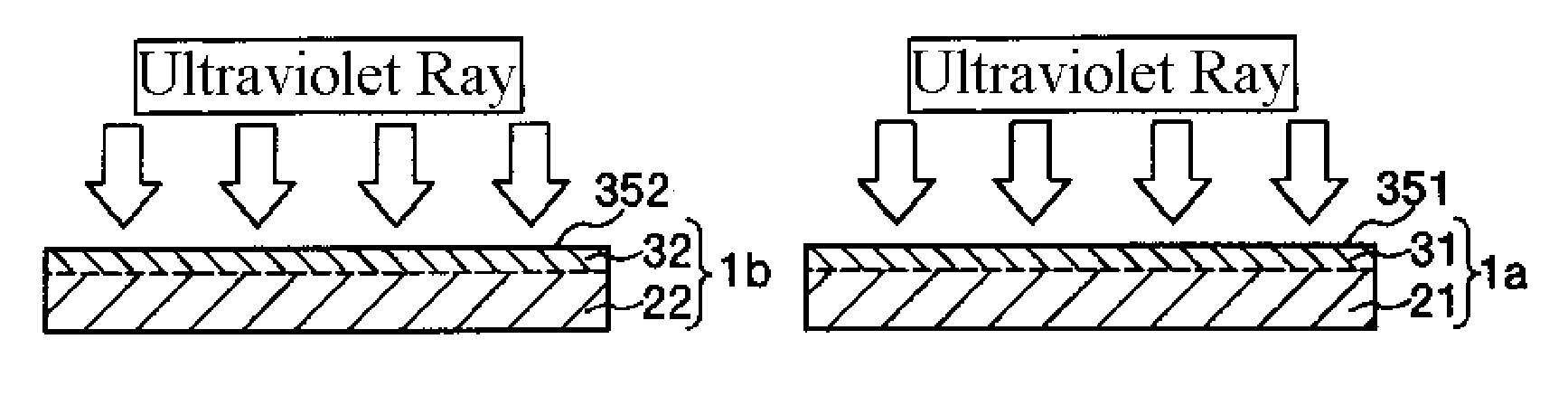
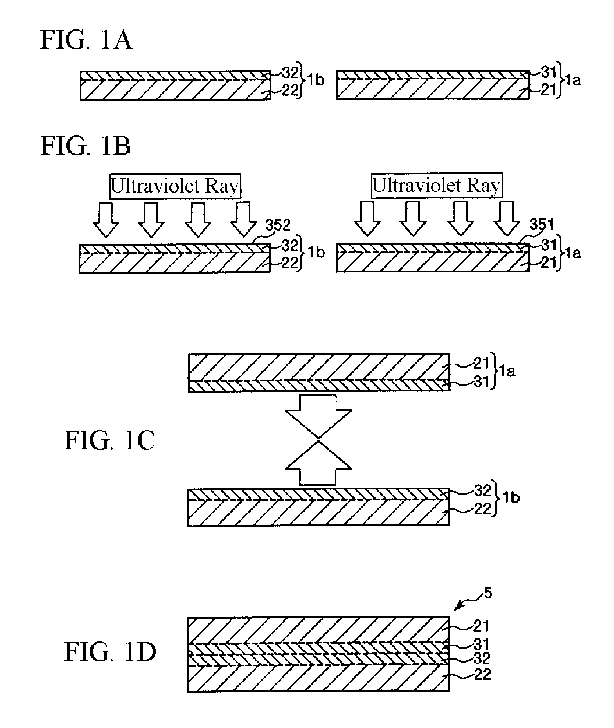
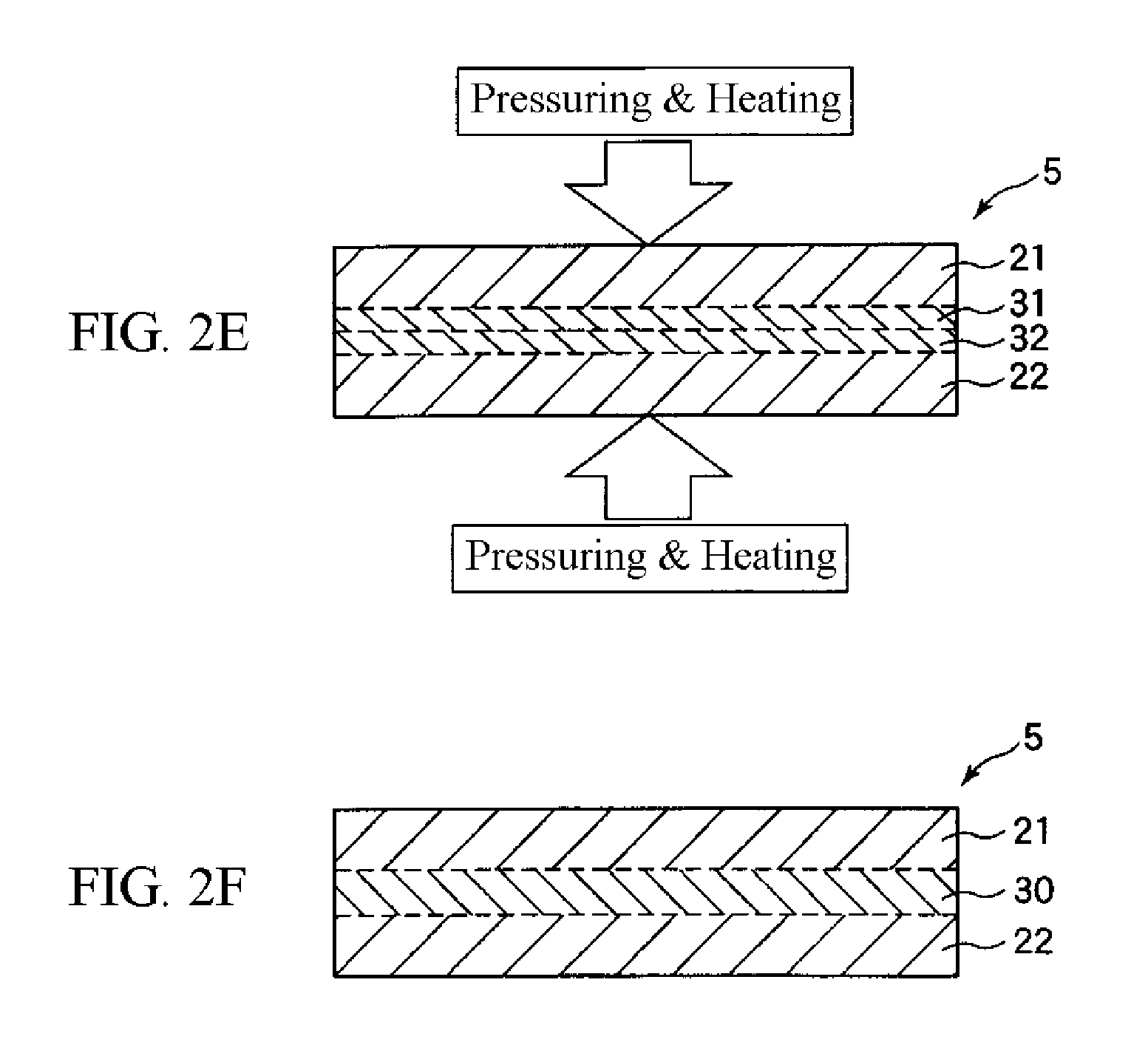
[0109]FIGS. 1A to 1D and 2E and 2F are longitudinal sectional views for explaining a first embodiment of a bonding method according to the present invention of bonding a substrate to an opposite substrate.

[0110]FIG. 3 is a partially enlarged view showing a state that before energy is applied to a bonding film in a bonded body according to the present invention.

[0111]FIG. 4 is a partially enlarged view showing a state that after energy is applied to a bonding film in a bonded body according to the present invention.

[0112]In this regard, it is to be noted that in the following description, an upper side in each of FIGS. 1A to 1D, 2E and 2F, 3 and 4 will be referred to as “upper” and a lower side thereof will be referred to as “lower”.

[0113]The bonding method according to this embodiment includes a step of preparing (providing) a base member (first obje...

second embodiment

[0318]Next, a description will be made on a second embodiment of each of a bonded body and a bonding method of the present invention.

[0319]FIGS. 7A to 7C are longitudinal sectional views for explaining a second embodiment of a bonding method according to the present invention of bonding a substrate to an opposite substrate. In this regard, it is to be noted that in the following description, an upper side in each of FIGS. 7A to 7C will be referred to as “upper” and a lower side thereof will be referred to as “lower”.

[0320]Hereinafter, the bonding method according to the second embodiment will be described by placing emphasis on the points differing from the first embodiment, with the same matters omitted from description.

[0321]The bonding method according to this embodiment is the same as that of the first embodiment, except that after the base member 1a and the base member 1b are laminated together, the energy is applied to the bonding films 31 and 32.

[0322]In other words, the bond...

third embodiment

[0343]Next, a description will be made on a third embodiment of each of a bonded body and a bonding method of the present invention.

[0344]FIGS. 8A to 8D are longitudinal sectional views for explaining a third embodiment of a bonding method according to the present invention of bonding a substrate to an opposite substrate. In this regard, it is to be noted that in the following description, an upper side in each of FIGS. 8A to 8D will be referred to as “upper” and a lower side thereof will be referred to as “lower”.

[0345]Hereinafter, the bonding method according to the third embodiment will be described by placing emphasis on the points differing from the first and second embodiments, with the same matters omitted from the description.

[0346]The bonding method according to this embodiment is the same as that of the first embodiment, except that two base members 1a and 1b each having a bonding film 31 or a bonding film 32 are prepared, a surface 351 of the bonding film 31 thereof and o...


PUM

PropertyMeasurementUnit
thicknessaaaaaaaaaa
refractive indexaaaaaaaaaa
wavelengthaaaaaaaaaa

Abstract

A bonded body according to the present invention comprises a first object comprised of a first substrate and a first bonding film formed on the first substrate and a second object comprised of a second substrate and a second bonding film formed on the second substrate. The first and second bonding films contain a Si-skeleton constituted of constituent atoms containing silicon atoms and elimination groups bonded to the silicon atoms of the Si-skeleton. The Si-skeleton includes siloxane (Si—O) bonds. The constituent atoms are bonded to each other. When an energy is applied to at least a part region of the surface of each of the first and second bonding films, the elimination groups existing in the vicinity of the surface within the region are removed from the silicon atoms of the Si-skeleton so that each region develops a bonding property with respect to the other film to thereby bond the first and second objects together through the first and second bonding films.

Description

CROSS-REFERENCE TO RELATED APPLICATION[0001]This application claims a priority to Japanese Patent Application No. 2007-182677 filed on Jul. 11, 2007 and Japanese Patent Application No. 2008-133671 filed on May 21, 2008 which are hereby expressly incorporated by reference herein in their entireties.BACKGROUND[0002]1. Technical Field[0003]The present invention relates to a bonded body and a bonding method.[0004]2. Related Art[0005]Conventionally, in the case where two members (base members) are bonded together, an adhesive such as an epoxy-based adhesive, an urethane-based adhesive, or a silicone-based adhesive has been often used.[0006]In general, an adhesive exhibits reliably high adhesiveness regardless of constituent materials of the members to be bonded. Therefore, members formed of various materials can be bonded together in various combinations.[0007]For example, a droplet ejection head (an ink-jet type recording head) included in an ink-jet printer is assembled by bonding, usi...

Claims


Application Information

Patent Timeline
Patent Type & Authority Applications(United States)
IPC IPC(8): B32B9/04B32B27/28B29C65/14B32B15/04
CPCB29C59/14B29C65/02B29C65/1403B29C65/1406B29C65/1432B29C65/1435B29C65/1496B29C65/16B29C65/1606B29C65/1616B29C65/1619B29C65/5057B29C65/52B29C65/528B29C66/004B29C66/02B29C66/30223B29C66/348B29C66/45B29C66/712B29C66/73111B29C66/919B29C2035/0827B29K2009/06B29K2021/00B29K2021/003B29K2023/00B29K2023/06B29K2023/083B29K2023/086B29K2023/12B29K2025/00B29K2027/06B29K2027/08B29K2027/12B29K2027/16B29K2027/18B29K2033/12B29K2055/02B29K2059/00B29K2063/00B29K2067/00B29K2067/006B29K2069/00B29K2071/00B29K2071/12B29K2075/00B29K2077/00B29K2077/10B29K2079/08B29K2079/085B29K2081/06B29K2096/005B29K2105/0079B29K2105/0085B29K2105/0088B29L2009/00B29L2031/767B41J2/161B41J2/1623C08J7/123C09J5/06H01L21/187B29C65/1483B29C65/5021B29C66/954B29C65/483B29C65/4835B29C65/4845B29C66/91411B29C66/9161Y10T428/2817Y10T156/10Y10T428/2826Y10T428/2848Y10T428/2809Y10T428/265Y10T428/2852B29C65/00B29C66/8322B29C66/83221B29C66/73113B29K2995/0027B29C66/73343B29C66/71B29C66/72325B29C66/72321B29C66/7234B29C66/72323B29C66/73112B29C66/1122Y10T428/31663H01L21/185B29K2081/04B29K2075/02B29K2067/06B29K2067/04B29K2067/003B29K2061/04B29K2033/08B29K2029/04B29K2025/08B29K2025/06B29K2023/18B29K2023/16
Inventor MATSUO, YASUHIDEOTSUKA, KENJIHIGUCHI, KAZUOWAKAMATSU, KOSUKE
Owner SEIKO EPSON CORP
Why Eureka
Try Eureka