
Improved autoinjector supporting the syringe at the front

a technology of auto-injector and syringe, which is applied in the direction of automatic syringe, infusion syringe, manufacturing tools, etc., can solve the problems of not directly maintaining sterility of medicament and needle, the sheath is likely to provide less mechanical protection, and the auto-injector cannot be operated with the needle sheath in place, so as to eliminate the risk of needle-stick injury

Active Publication Date: 2010-06-17
SHL MEDICAL AG
View PDF60 Cites 70 Cited by
  • Summary
  • Abstract
  • Description
  • Claims
  • Application Information

AI Technical Summary

Benefits of technology

[0024]Preferably, the autoinjector is a single-use autoinjector. The simple construction of the autoinjector makes it very appropriate for applications such as emergency use for injecting a large population to control a pandemic, where a large number of cost-effective disposable autoinjectors are required. A single-use autoinjector also provides a very convenient means for patients to administer their own injections, even if lacking in dexterity and / or clinical experience. Delivery of viscous drugs is particularly problematic for patients lacking dexterity because of the greater force needed to deliver such drugs—this problem being alleviated by the present invention.
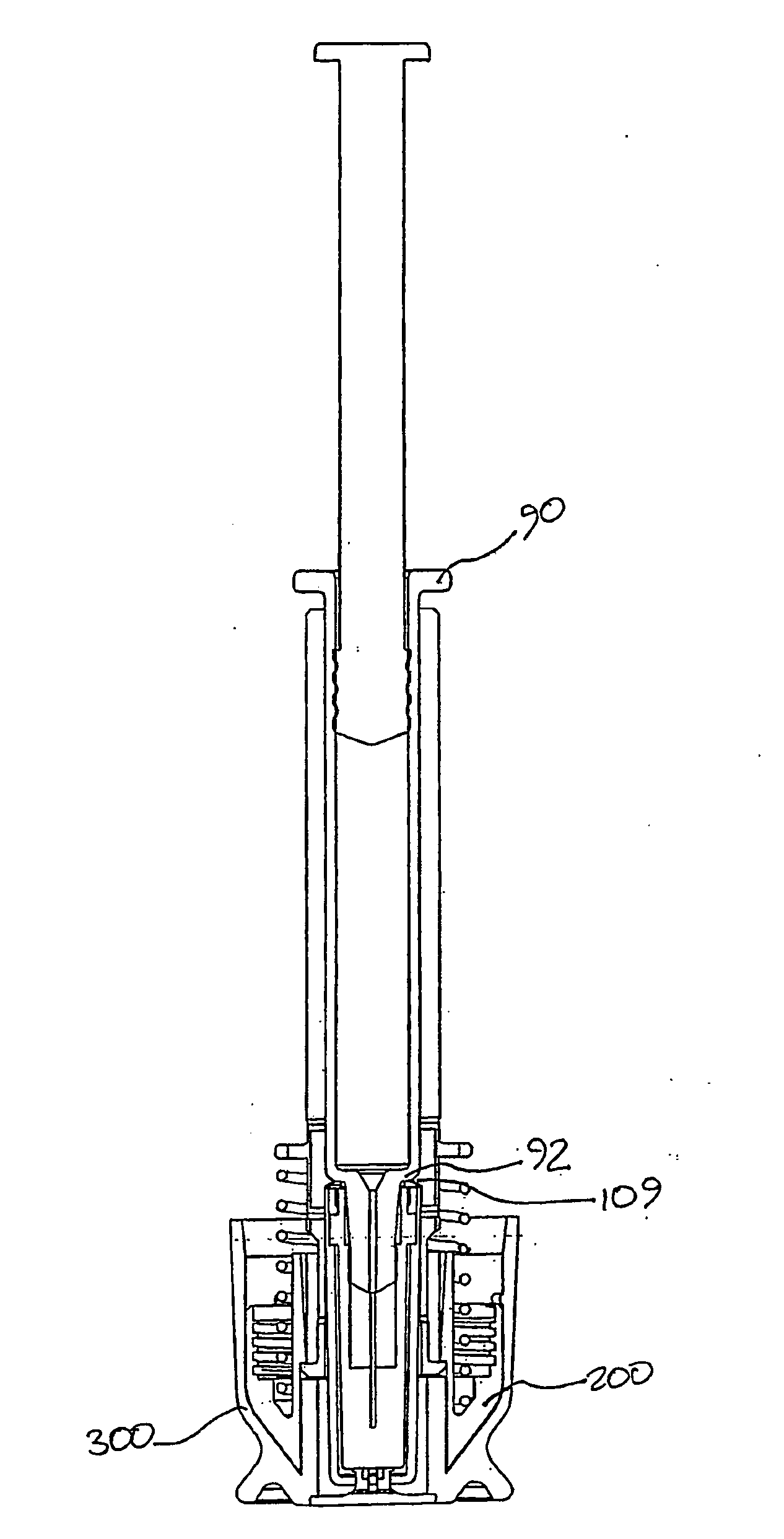
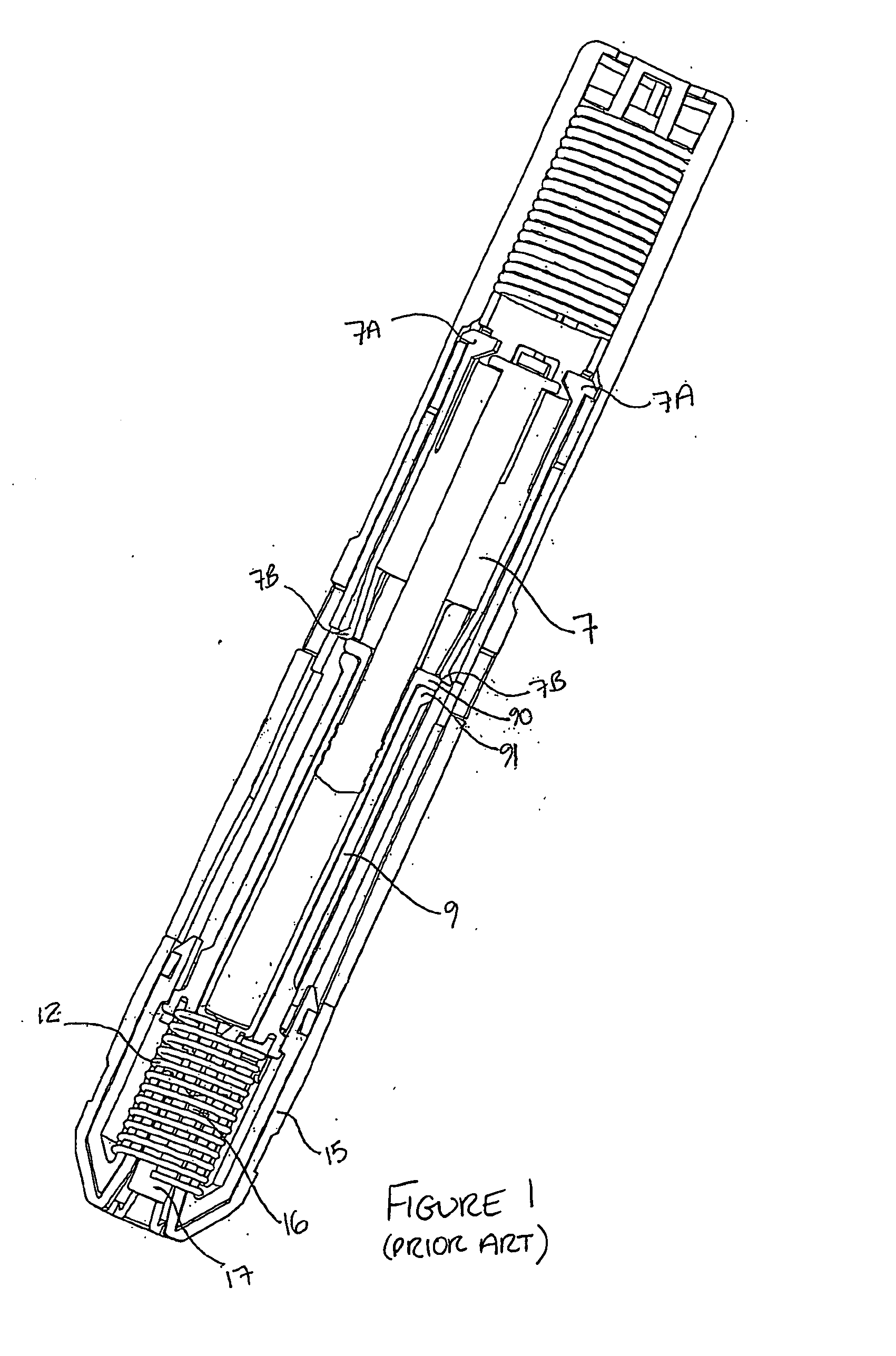
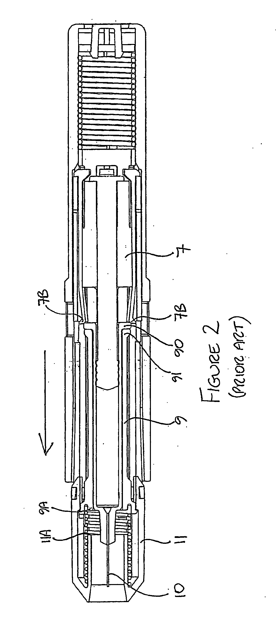
[0026]Preferably, the syringe is axially moveable in said housing and is biased so that the needle is normally wholly inside said housing, wherein before injection the syringe is movable axially so as to move at least a part of said needle out of the housing and wherein after injection, the syringe is able to retract in order to retract said part of said needle into the housing. The concealment of the needle both before and after injection makes the autoinjector particularly suitable where the patient has any aversion to injection by needle. Retraction and retention of the needle after injection eliminates the risk of needle-stick injury.

Problems solved by technology

The autoinjector cannot be operated with the needle sheath in place.
In other words, this type of rupturable needle sheath does not need to be removed from the device before actuation, however, such needle sheaths are likely to provide less mechanical protection than those provided in a standard pre-filled syringe presentation and usually do not directly maintain sterility of the medicament and the needle.
Any modification to the standard syringe may require further trials and approval, adding delay and expense.
However, glass is notoriously fragile and there is a risk of damage or breakage of the syringe during injection if the forces to which the syringe is subjected by the injection device are not properly controlled.
This tension is undesirable in a glass barrel, which may become damaged or broken, especially if the medicament comprises a particularly viscous liquid which requires greater force to expel it from the syringe via the needle.
However, for a given length of needle, the smaller the needle diameter, the greater the force required to eject the medicament from the syringe.
An increase in the forces on the syringe consequently increases the likelihood of the syringe breaking during the injection.
The risk of the syringe breaking during injection is significant, and is not only inconvenient and costly but is also potentially dangerous.
If breakage occurs, it is possible that glass fragments and / or the needle may become detached and exit the front of the device causing injury.
Furthermore, there is the risk that the remaining medicament will leak or be ejected from the device in an uncontrolled manner, potentially delivering the wrong dose into the patient, or causing injury e.g. if the medicament contacts the patient's skin or eyes.
These problems are amplified when the medicament is viscous as a more powerful energy source is needed in such applications so that the forces involved are greater.

Method used


Image

  • Improved autoinjector supporting the syringe at the front
  • Improved autoinjector supporting the syringe at the front
  • Improved autoinjector supporting the syringe at the front

Examples


Embodiment Construction

[0065]Throughout the description and claims of this specification, the words “comprise” and “contain” and variations of the words, for example “comprising” and “comprises”, means “including but not limited to”, and is not intended to (and does not) exclude other components, integers or steps.

[0066]Throughout the description and claims of this specification, the singular encompasses the plural unless the context otherwise requires. In particular, where the indefinite article is used, the specification is to be understood as contemplating plurality as well as singularity, unless the context requires otherwise.

[0067]Throughout the following description, reference to a “forward” direction means the direction which is towards the patient when the injection device is in use. The “forward” end of the injection device is the end nearest the patient's skin when the device is in use. Similarly, reference to a “rearward” direction means the direction which is away from the patient and the “rea...


PUM

PropertyMeasurementUnit
volumeaaaaaaaaaa
axial compressive forceaaaaaaaaaa
mechanical damageaaaaaaaaaa

Abstract

An autoinjector comprising a housing in which can be mounted a syringe comprising a barrel for holding a volume of medicament, a needle at one end of the barrel in fluid communication with the medicament and a plunger axially-moveable in the barrel to a forwardmost position, the autoinjector further comprising a syringe support means for supporting the barrel at an axial location at or forward of the forwardmost position of the plunger and having a reaction surface for the syringe, whereby in use said reaction surface (109) provides an axial compressive force on said barrel when a forward axial force is applied to the plunger.

Description

[0001]This invention relates to the field of autoinjectors for the administration of liquid medication, for example, interferon.BACKGROUND[0002]An autoinjector is an automatic injection device designed to facilitate automated delivery of a dose of medicament to a patient through a hypodermic needle, the injection usually being administered by the patient themselves. An autoinjector works, for example, by delivering an injection automatically upon actuation by the patient pressing a button, moving a lever or part of a housing etc. This is in contrast to a conventional manual syringe where the patient himself needs to directly depress a plunger into a barrel containing medicament in order to effect the injection. The terms “autoinjector” and “injection device” are used interchangeably in the following description.[0003]Examples of autoinjectors are described in WO2003 / 099358 (Seedlings Life Science Ventures LLC) and WO01 / 93926 (Mayo Foundation for Medical Education and Research). Thes...

Claims


Application Information

Patent Timeline
Patent Type & Authority Applications(United States)
IPC IPC(8): A61M5/32A61M5/50B23P11/00
CPCA61M5/2033Y10T29/49826A61M2005/206A61M5/3134A61M5/3202A61M5/3204A61M5/326A61M2005/2407A61M5/24A61M2005/244A61M5/32A61M5/20A61M5/3129A61M2005/3118
Inventor STAMP, KEVIN
Owner SHL MEDICAL AG
Learn More