Advanced burr, applique for a burr and method of fabricating

a burr and applique technology, applied in the field of advanced burrs and appliques for burrs, can solve the problems of affecting the operation of the operator, affecting the operation of the patient, so as to achieve excellent operation and material removal characteristics, excellent wear resistance and lubricity

Inactive Publication Date: 2010-06-17
HOLKO KENNETH +1
View PDF3 Cites 3 Cited by
  • Summary
  • Abstract
  • Description
  • Claims
  • Application Information

AI Technical Summary

Benefits of technology

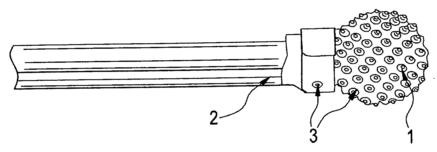
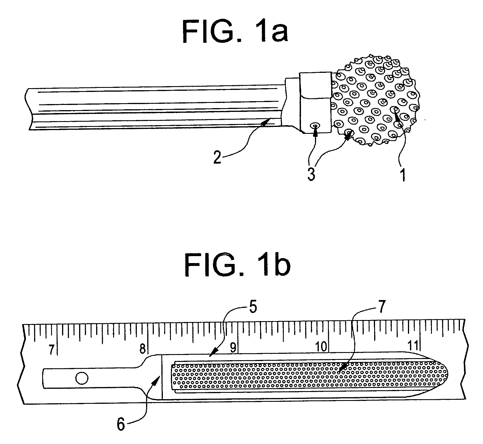
[0005]The present invention relates to an abrading device comprising an advanced burr and appliqué for a burr and a new process for making cutting tools for fine material removal applications such as bone and tissue surgeries. An appliqué sheet is first engineered by CAD with an abrading surface comprising cutting facets designed for the particular application. The appliqué is attached to a surface of a tool blank comprising a burr or abrader tool blank and then metallurgically bonded and coated by the BRAZOL® or Co—P process. The tool blank has a proximal shank a...

Problems solved by technology

Particles released from the tool at high speed also present a safety hazard to the operator.
Two problems with this technique are (1) a “kickback” effect when the flutes first make contact, and (2) limitation in flute size, shape and geometry as dictated by the machining process used to create the cutting surface on the burr.
This kickback effect can damage surrounding tissue and other material, while size and shape limitations direct usage toward more coarse removal applications.
Burr operational speed has been increased to minimize kickback, but this makes the burr more dangerous to use.
While this technique can minimize kickbac...

Method used


Image

  • Advanced burr, applique for a burr and method of fabricating
  • Advanced burr, applique for a burr and method of fabricating
  • Advanced burr, applique for a burr and method of fabricating

Examples


Embodiment Construction

[0023]The process of the present invention begins by designing a cutting surface pattern by computer aided design (CAD) as seen in FIGS. 2a-4b. The preferred cutting facet layouts are shown in these figures. Also shown are the protrusions or plateaus and cutting edges that will be present on the final appliqué. Three exemplary designs are described but an unlimited number of designs are possible with various cutting facet sizes, shapes, orientations, spacings, and depths.

[0024]With reference to FIGS. 2a and 2b, a first example of a cutting facet layout in accordance with the teachings of the present invention is shown to include a plurality of protrusions 11 and a plurality of smaller holes 13. As seen in the photomicrograph of FIG. 2b, the protrusions 11 are generally cylindrical at their distal terminations and widen out proximally as they approach the base of the appliqué10. The smaller holes 13 are located such that, as best seen in FIG. 2a, six holes 13 surround each protrusion...


PUM


Abstract

An abrading device consists of an advanced burr and appliqué for a burr and a new process for making cutting tools for fine material removal applications such as in bone and tissue surgeries. An appliqué sheet is first engineered by CAD with an abrading surface having cutting facets. The appliqué is attached to a surface of a tool blank and then metallurgically bonded and coated by the BRAZOL® or Co—P process. The tool blank has a proximal shank attachable to a driver and a distal surface to which the appliqué is affixed. Since each facet is attached to surrounding facets and then strongly bonded to the tool, the facets do not dislodge when used to abrade a surface of an object. The BRAZOL® or Co—P coating imparts excellent wear resistance and lubricity to the cutting facets. This results in excellent operational and material removal characteristics. This approach to making surgical and fine industrial tools offers engineered flexibility in design rather than process dependent designs.

Description

BACKGROUND OF THE INVENTION[0001]The present invention relates to an advanced burr, appliqué for a burr and method of fabricating. Burr and abrading tools are well known in the medical and manufacturing industries. These tools are used to remove various materials, usually in finish or “fine” work where careful control of amount of material removed is important. Also, these tools must not damage surrounding tissue or machined surfaces either by impact with the surface or by leaving behind particles removed from the tool during abrading operations. Particles released from the tool at high speed also present a safety hazard to the operator.[0002]One well known manufacturing technique is to machine flutes or cutting surfaces in a burr or abrader surface. When operated in a rotational or oscillatory mode, these flutes dig into the object surface and scrape material off. Two problems with this technique are (1) a “kickback” effect when the flutes first make contact, and (2) limitation in ...

Claims


Application Information

Patent Timeline
IPC IPC(8): A61B17/00A61B17/32A61B17/56
CPCA61B17/1615A61B17/32002A61B17/1659
Inventor HOLKO, KENNETHPETERSEN, THOMAS D.
Owner HOLKO KENNETH
Why Eureka
Try Eureka