Ureteral Stent

a ureteral stent and ureteral tube technology, applied in the field of improved stents, can solve problems such as significant patient discomfort, and achieve the effects of significant hydrophilicity or hydrophobicity, reduced rigidity or stiffness, and more rigidity

Active Publication Date: 2010-06-17
BOSTON SCI SCIMED INC
View PDF0 Cites 19 Cited by
  • Summary
  • Abstract
  • Description
  • Claims
  • Application Information

AI Technical Summary

Benefits of technology

[0009]In one aspect of the invention, a ureteral stent, comprising a renal coil at a renal end; a wick portion coupled to the renal coil and extending from an intersection with the renal coil to a bladder end; wherein the wick portion may be more rigid than the renal coil in a proximate end of the wick portion, proximate the renal coil, decreasing in rigidity or stiffness along the length of the wick portion, and the wick portion has significant hydrophilicity or hydrophobicity as compared to that of the renal coil. The renal coil may have a length from a tapered proximal end to a tapered distal end such that the distal end is located proximate a ureteropelvic junction of a patient when the renal coil is inserted into a kidney of a patient with the aid of a guidewire. In addition, the wick portion further may comprise a core and a sheath, the core comprising a material having an elasticity greater than an elasticity of the sheath.
[0010]The stent may further comprise a coupler joining the renal coil to the wick portion, and the coupler may one or more of: at least one clamp, a receiver in a distal end of said renal coil, sutures and / or an adhesive. The renal coil and wick may also be one continuous member of the same hydrophilic or hydrophobic material.

Problems solved by technology

Stents of this type suffer from the problem that stents of multiple sizes must be created and then a physician must select what size stent to use based on approximations of the patient's physiology.
In addition, even with the reduced size of the strands or loops, significant patient discomfort may result.

Method used


Image

  • Ureteral Stent
  • Ureteral Stent
  • Ureteral Stent

Examples


Embodiment Construction

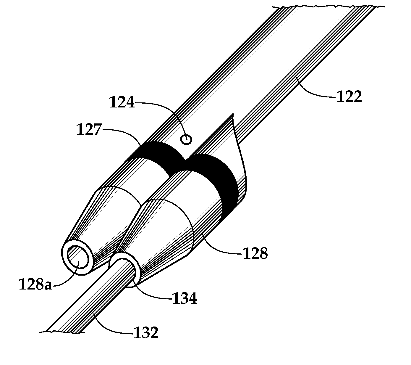
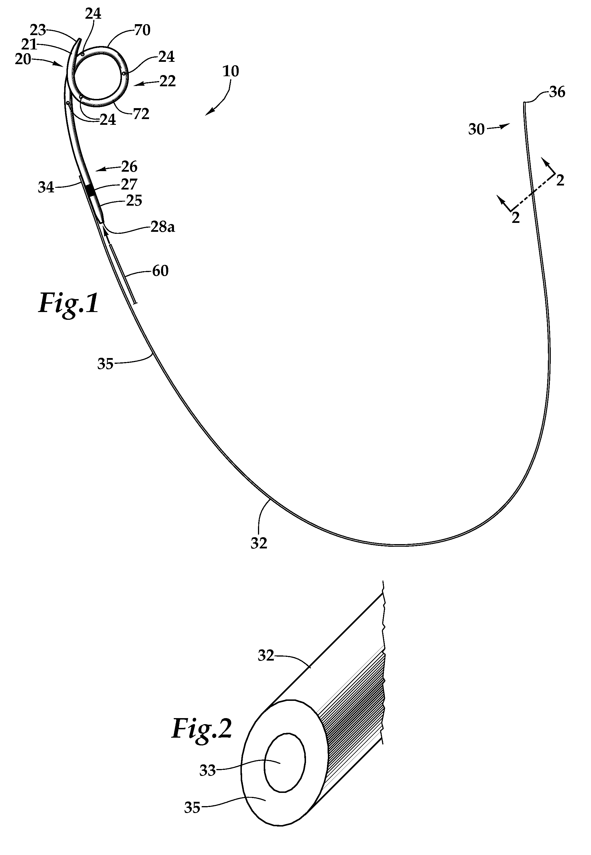
[0025]As seen in FIG. 1, a stent such as ureteral stent 10 comprising a renal coil 22 at a renal end 20 and wick portion 32 extending from renal coil 22 to a bladder end 30.

[0026]Renal coil 22 may comprise a flexible coiled material such as a rubberized or polymerized material. As its name implies, renal coil 22 may be coiled at renal end 20 of stent 10 for locating and maintaining renal end 20 inside kidney 2, preferably proximate renal pelvis 3. Renal coil 22 may be spiral shaped or generally J-shaped, or it may have other configurations that will keep renal end 20 from migrating out of kidney 2. Moreover, renal coil 22 may have a tapered end 23 at the proximal end of stent 10, which may facilitate insertion of stent 10. Furthermore, renal coil 22 may have a tapered end 25 for ease of stent 10 removal.

[0027]In addition, renal coil 22 may be a generally tubular material having an outer diameter of between about 3 Fr. and about 10 Fr., preferably between about 5 Fr. and about 7 Fr.,...


PUM


Abstract

A ureteral stent comprising a short renal coil made of a pliable material and a wick portion made of a material having a hydrophilicity or hydrophobicity different from that of the renal coil and extending from a ureteropelvic junction to a bladder so as to assist in the transfer of urine out of a kidney and into the bladder and to improve patient comfort. Due to increased hydrophilicity or hydrophobicity, wick may be significantly smaller in diameter than renal coil, resulting in less reflux of urine into the kidney and further decreasing patient discomfort. The stent may further comprise one or more couplers between the renal coil and wick portion, such as clamps, couplers, sutures, adhesives or receiving ends of the renal coil, and the wick portion may further comprise a sheath surrounding an elastic core to prevent kinking and enhance the ability of the wick portion to move with the patient. A novel method of ureteral stent placement is also disclosed.

Description

BACKGROUND OF THE INVENTION[0001]1. Field of the Invention[0002]The present invention is directed to an improved stent, for example a ureteral stent.[0003]2. Description of the Related Art[0004]A ureteral stent is used to aid in transfer of urine from one of a patient's kidneys to the patient's bladder where obstructions or other conditions may inhibit normal flow, typically by creating a path around a blockage. While the stent is used to allow for free flow of urine, the stent itself should stay in place and not migrate out of or further into the kidney, or out of or further into the bladder.[0005]In the past, ureteral stents consisted of hollow tubes having spirals or loops at both ends. The spirals caused both ends of the stent to deviate from a generally linear or tubular shape, forming structures that would less easily lead to migration of the stent. In addition, in these stents, urine would flow through the center of the tube, while the walls of the tube prevented obstructions...

Claims


Application Information

Patent Timeline
Patent Type & Authority Applications(United States)
IPC IPC(8): A61F2/04A61M5/00A61B19/00
CPCA61F2002/048A61F2/04A61F2220/0033A61F2220/005A61F2250/0018A61F2250/0019A61F2250/0029A61F2250/0039A61F2250/0056A61F2250/0098A61M27/008
Inventor CHUNG, STEVEN Y.
Owner BOSTON SCI SCIMED INC
Why Eureka
Try Eureka