System and Method For the Separation of Analytes

an analyte and protein technology, applied in the field of proteomics and protein detection, can solve the problems of inefficiency, unreliability, and high cost of available systems and methods for analyte separation and protein detection, and achieve the effect of facilitating sample separation

Inactive Publication Date: 2010-06-24
LEIDOS +1
View PDF19 Cites 43 Cited by
  • Summary
  • Abstract
  • Description
  • Claims
  • Application Information

AI Technical Summary

Benefits of technology

[0016]It is a further object of the current invention to replace current HPLC systems with a lower cost, portable, high efficiency, high throughput microfluidic system or systems that require less sample, i.e., less than 1 μl, and solvent volumes, and that provide faster and more consistent protein separations.
[0017]It is a further object of the current invention to utilize CIEF to first fractionate analytes by pI in at least one microchannel on a miniaturized chip platform that allows for analyte introduction, separation into proteins, and detection of separated proteins.
[0018]It is a further object of the current invention to utilize CE to separate the pI fractions in at least a one microchannel that is perpendicular to the at least one CIEF microchannel according to mass / charge for each protein on a miniaturized chip platform that allows for analyte introduction, separation into proteins, and detection of separated proteins.
[0021]According to a third embodiment of the present invention there is described a system for separating a sample. The system includes means for introducing a sample into a first microchannel formed in a module; means for separating the sample into a plurality of sub-samples based on the varying isoelectric points of the plurality of sub-samples; means for causing a first of the plurality of sub-samples to enter a first of a plurality of second parallel microchannels integrally connected to the first microchannel; means for separating the first of the plurality of sub-samples into a plurality of protein components according to electrophoresis; means for applying opposite charges to either end of the first microchannel to facilitate separating the sample into a plurality of sub-samples; means for applying a first charge to the non-intersecting end of a third microchannel integrally connected to the first microchannel and applying a second, opposite charge to the non-intersecting end of the first of the plurality of second microchannels to facilitate the first of the plurality of sub-samples entering the first of the plurality of second microchannels and further separating according to electrophoresis; means for aligning a first detector with the first microchannel in order to detect the separation of the sample into the plurality of sub-samples based on varying isoelectric points of the plurality of sub-samples within the first microchannel; means for aligning a second detector with the non-intersecting end of the first of the plurality of second microchannels; and means for detecting the plurality of protein components for the first of the plurality of sub-samples.

Problems solved by technology

Available systems and methods for analyte separation and protein detection are inefficient, expensive and unreliable due to the physical limitations of the current systems.

Method used


Image

  • System and Method For the Separation of Analytes
  • System and Method For the Separation of Analytes
  • System and Method For the Separation of Analytes

Examples


Embodiment Construction

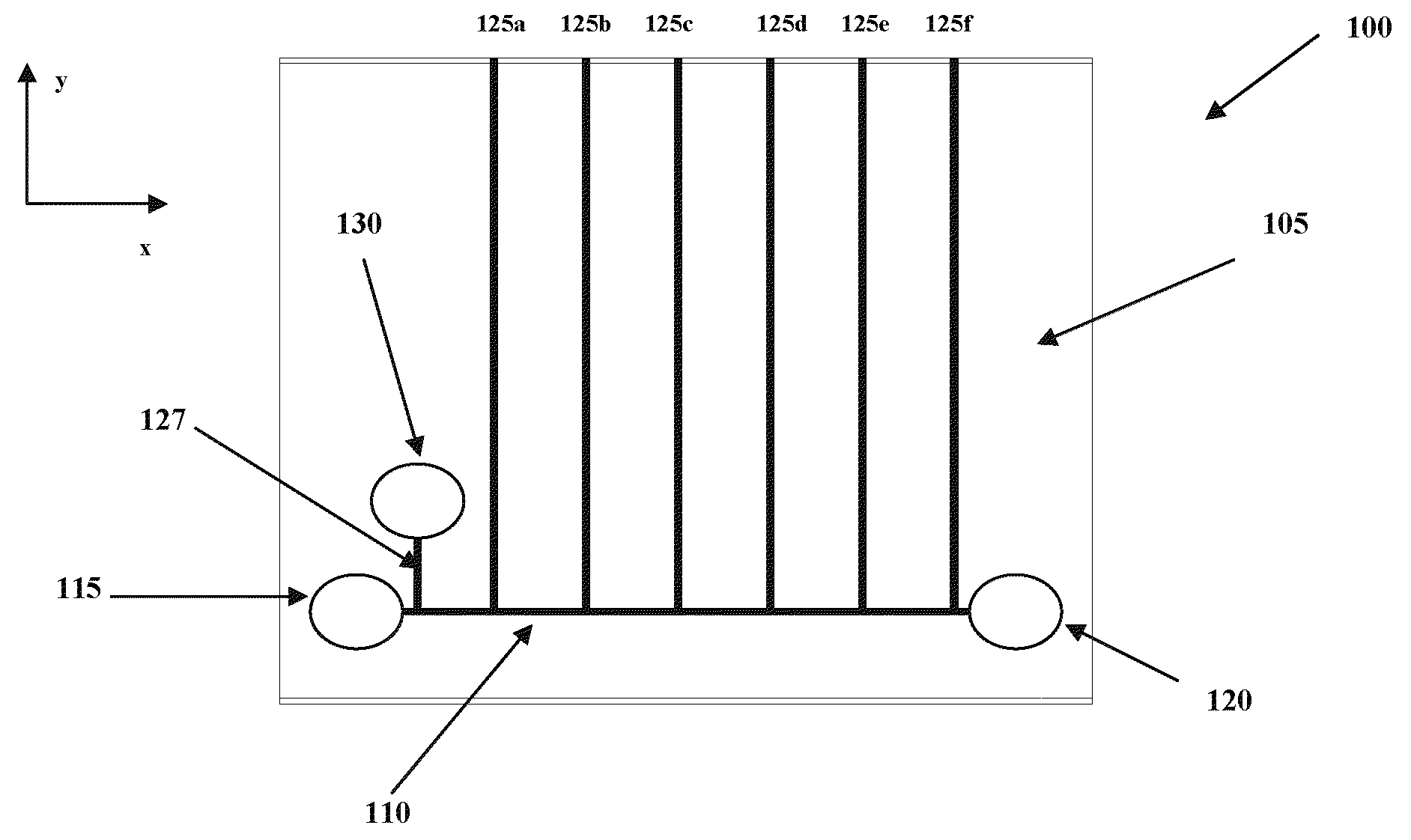
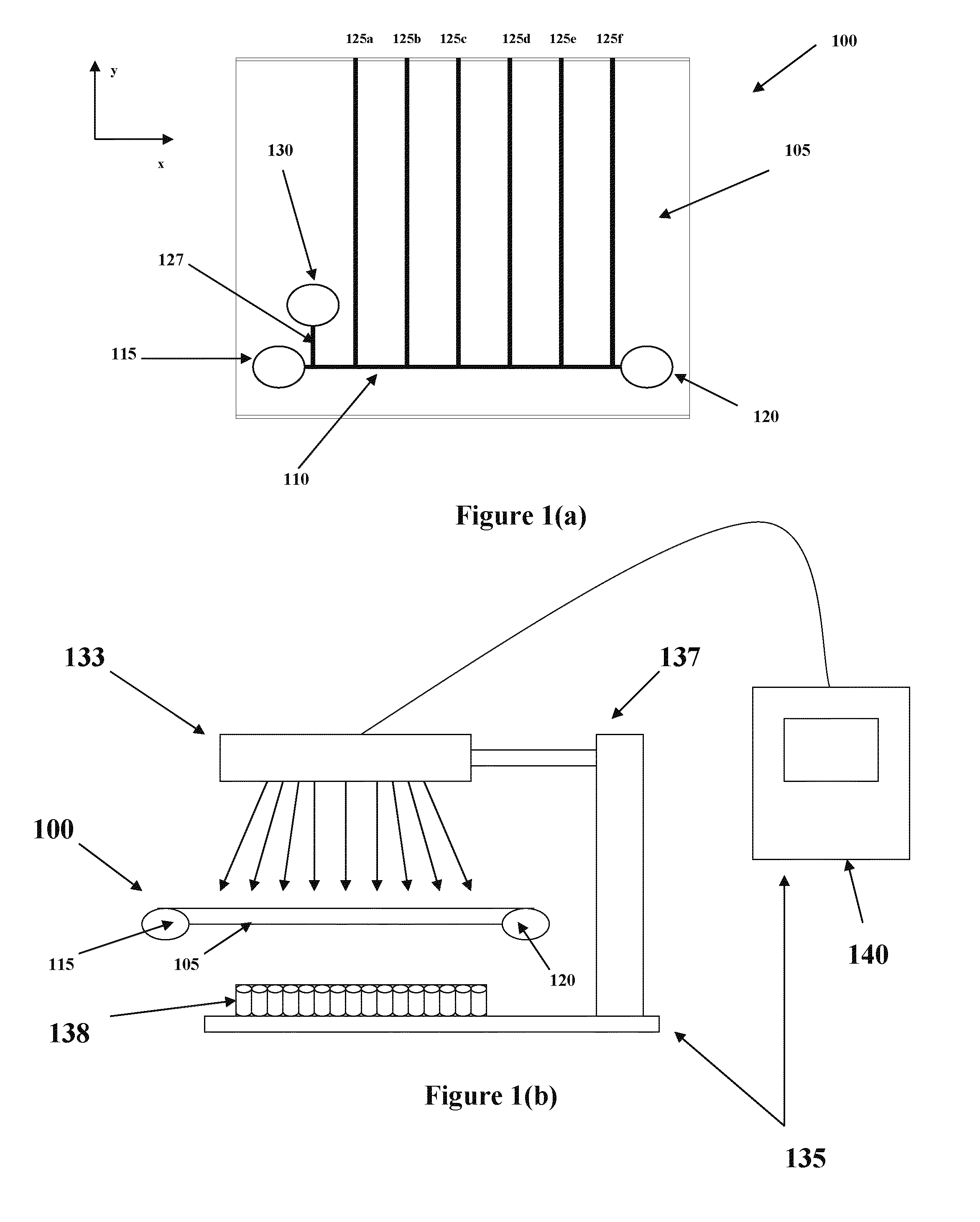
[0027]In a preferred embodiment of the present invention, CIEF and CE are combined on a semiconductor, e.g., silicon, chip forming a two-dimensional separations module 100 for facilitating two types of analyte separation and subsequent protein detection. Throughout the specification, the word protein will be used to refer to the protein molecule itself and / or one or more of its basic components, i.e., peptides, polypeptides, oligopeptides, amino acids and the like, except where specific reference is made to the individual components. As shown in FIG. 1(a), a chip 105 includes a first microchannel or microcapillary (hereafter “microchannel”) 110 extending in the X direction, having reservoirs 115, 120 at opposite ends thereof. Intersecting with the first microchannel 110 are a plurality of second microchannels, 125a-f extending in the Y direction, perpendicular to the first microchannel 110. Additionally, there is a third microchannel 127 also extending in the Y-direction for supplyi...


PUM

PropertyMeasurementUnit
volumesaaaaaaaaaa
widthaaaaaaaaaa
voltageaaaaaaaaaa

Abstract

A separation module operates to fractionate or separate an analyte into fractions according to pI, i.e., pI bands, utilizing capillary isoelectric focusing (“CIEF”) within a first microchannel. The fractions are stacked to form plugs, the number of which is determined by a number of parallel second microchannels integrally connected to the first microchannel, into which the fractions are directed according to the buffer characteristics found in each of the individual microchannels. Within the microchannels the plugs are separated into proteins according to a different chemical property, i.e., “m / z,” utilizing capillary electrophoresis (“CE”).

Description

CROSS-REFERENCE TO RELATED APPLICATIONS [0001]The present application is a divisional application of U.S. patent application Ser. No. 10 / 372,799 entitled “System and Method For the Separation of Analytes,” filed Feb. 26, 2003, and which is incorporated herein by reference.BACKGROUND OF THE INVENTION [0002]1. Field of the Invention[0003]Generally, the invention relates to the field of analyte separation and protein detection, referred to commonly as proteomics. More particularly, the invention relates to the separation of analytes and detection of separated proteins using microfluidics and chip-based technologies.[0004]2. Description of the Related Art[0005]A key step to proteomic research is the ability to separate, isolate and independently detect proteins, i.e., hormones, enzymes, antibodies, etc. or more basically, peptides, polypeptides, amino acids and the like, within an analyte or sample (hereafter “analyte”).[0006]Heretofore, the most-widely used, but often most technically ...

Claims


Application Information

Patent Timeline
Patent Type & Authority Applications(United States)
IPC IPC(8): G01N27/26B01D57/02
CPCG01N33/558G01N27/44721G01N27/44791G01N27/44795
Inventor SCHNEIDER, THOMAS WAYNEBARANIUK, JAMES N.
Owner LEIDOS
Why Eureka
Try Eureka