Magnetic resolver and method of manufacturing the same

a resolver and magnetic technology, applied in the direction of magnets, magnet bodies, instruments, etc., can solve the problems of inferior yield rate, 3921 fails to disclose the specific configuration of the substrate on which the thin-film coil is mounted, and becomes unnecessary to wind wire. , to achieve the effect of improving the yield ra

Inactive Publication Date: 2010-06-24
TOYOTA JIDOSHA KK +1
View PDF2 Cites 33 Cited by
  • Summary
  • Abstract
  • Description
  • Claims
  • Application Information

AI Technical Summary

Benefits of technology

[0007]The present invention provides a magnetic resolver in a shape obtained by dividing an annular resolver, thus, allowing a plurality of substrates to be produced from a substrate material, thereby improving the yield rate, and provides a method of manufacturing the magnetic resolver.
[0009]A magnetic resolver according to a second aspect of the present invention is similar to that of the first aspect of the present invention, except that the substrate piece is a laminated substrate piece that is obtained by laminating a plurality of substrate pieces, on each of which at least one patterned coil is formed. With the magnetic resolver according the second aspect of the present invention, it is possible to achieve a necessary number of windings of coils without increasing the diameter of the magnetic resolver.
[0010]A magnetic resolver according to a third aspect of the present invention further includes: an annular cover that covers the coil substrate from above, sandwiching the coil substrate between the annular cover and the stator portion, and that integrates the stator portion and the coil substrate. The connection terminal for electrically connecting the patterned coils formed on their respective substrate pieces may be integrally formed with the cover. With the magnetic resolver according to the third aspect of the present invention, it is possible to easily establish an electric connection between the patterned coils of different substrate pieces.

Problems solved by technology

In addition, it becomes unnecessary to wind wire to obtain coils.
However, JP 5-3921 fails to disclose a specific configuration of a substrate on which the thin-film coils are formed.
If a doughnut-shaped (annular) substrate is used as described in JP 7-79542 cited above, an inferior yield rate is brought about when a plurality of annular substrates are cut out of a substrate material.

Method used


Image

  • Magnetic resolver and method of manufacturing the same
  • Magnetic resolver and method of manufacturing the same
  • Magnetic resolver and method of manufacturing the same

Examples


Embodiment Construction

[0023]Embodiments of the invention will be described below with reference to the drawings.

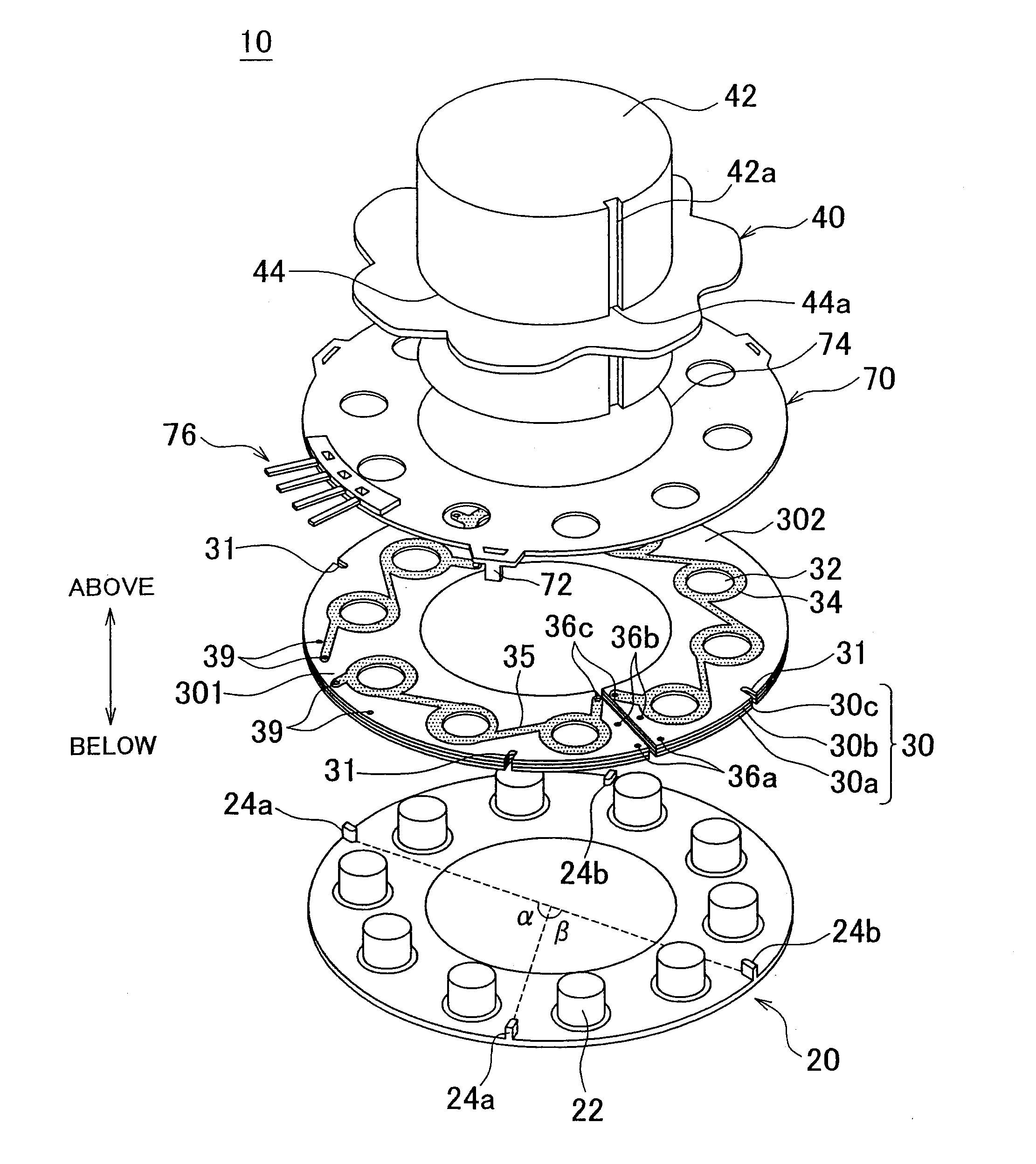
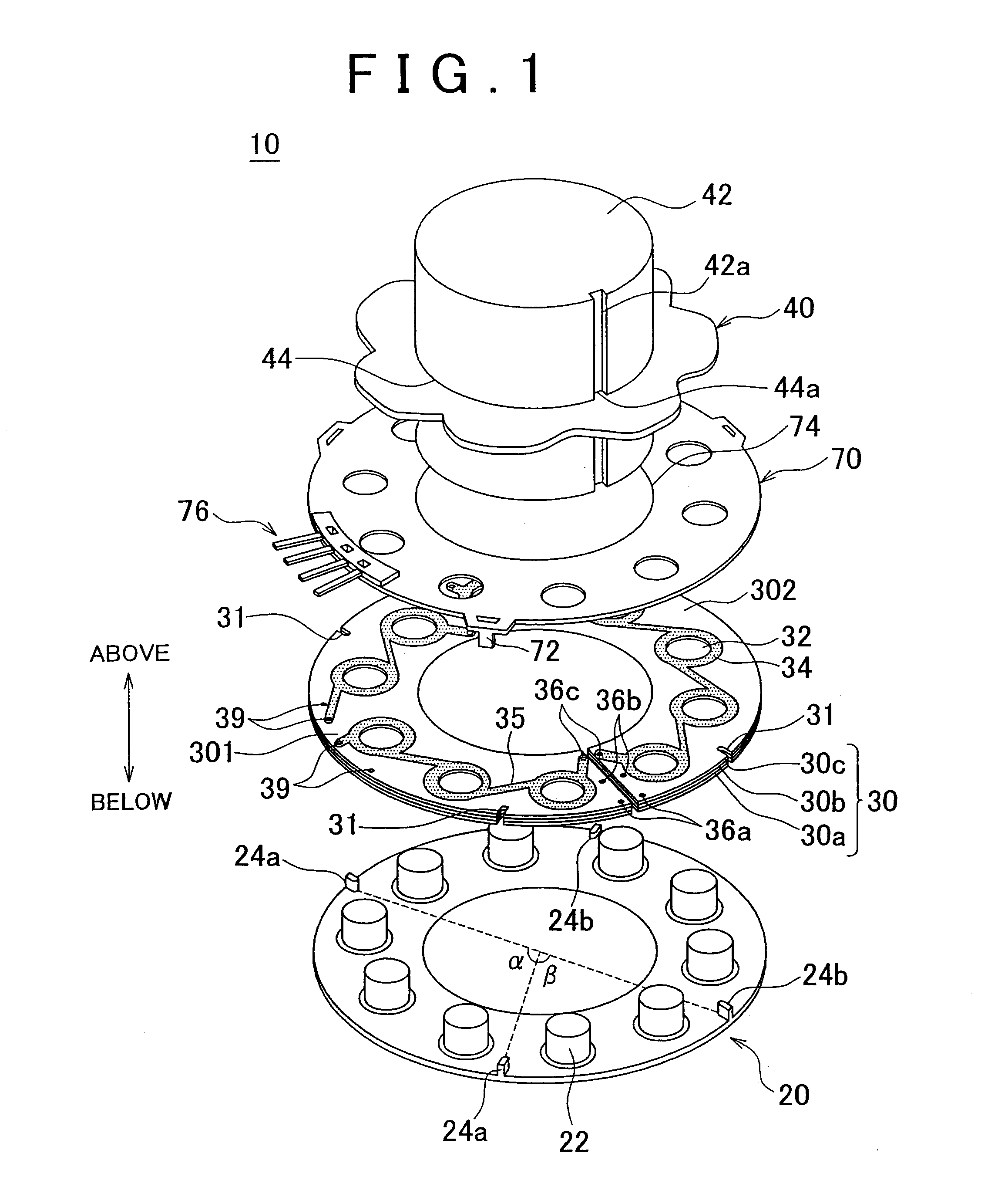
[0024]FIG. 1 is an exploded perspective view showing an embodiment of a magnetic resolver according to the present invention. In the description and the appended claims, the “above” direction does not necessarily mean the vertically upward direction in a state where the magnetic resolver is installed, but means the direction in which a rotor portion is present relative to a stator portion along the rotation axis, regardless of the orientation of the magnetic resolver once installed.

[0025]The magnetic resolver 10 of this embodiment is a variable reluctance (VR) resolver, and, as shown in FIG. 1, includes: a base plate 20 constituting the stator portion; a substrate 30 (hereinafter referred to as “the coil substrate 30”) on which coil portions are formed; and a rotor plate 40 constituting the rotor portion. As shown in FIG. 1, each of the base plate 20, the coil substrate 30, and the rotor plate ...


PUM

PropertyMeasurementUnit
voltageaaaaaaaaaa
rotation angleaaaaaaaaaa
electricallyaaaaaaaaaa

Abstract

A magnetic resolver that includes: an annular stator portion having a protruding core; an annular coil substrate on which a coil portion, which is disposed around the protruding core, is formed as a patterned thin-film coil; and a rotor portion disposed to face the stator portion from above, with the coil substrate interposed therebetween, wherein the amount of overlap between a top face of the protruding core and the rotor portion, when viewed from above, varies as a rotation angle of the rotor portion relative to the stator portion varies. The annular coil substrate may be constituted of substrate pieces that have shapes obtained by dividing the annular shape, which facilitates increasing the yield rate in the number of substrate pieces that can be produced from a substrate material.

Description

BACKGROUND OF THE INVENTION[0001]1. Field of the Invention[0002]The present invention relates to a magnetic resolver, the construction of which enhances the productivity in making the magnetic resolver, and a method of manufacturing the same.[0003]2. Description of the Related Art[0004]An electric motor controller that includes a Hall IC (integrated circuit) for detecting the position of a rotor may be manufactured by forming a printed board having a doughnut shape that surrounds the shaft of the rotor. Then, a first cutout is made in the printed board on the inner-diameter side of the doughnut-shaped printed board to provide the Hall IC therein, and a second cutout in the printed board on the outer-diameter side thereof to draw out the leads (see, Japanese Patent Publication No. 7-79542 (“JP 7-79542”), for example).[0005]Generally, conventional magnetic resolvers include a rotatable rotor core; a stator core, with two stator plates that sandwich the rotor core from above and below,...

Claims


Application Information

Patent Timeline
Patent Type & Authority Applications(United States)
IPC IPC(8): G01B7/30H01F7/06
CPCG01D5/2046Y10T29/4902H02K24/00H02K3/26G01D5/208
Inventor NISHIGUCHI, MASAYUKISEKITOMI, YUJIKIMURA, TOSHIHIRO
Owner TOYOTA JIDOSHA KK
Why Eureka
Try Eureka