Methods and System for Determining a Dominant Impairment of an Impaired Communication Channel

a communication channel and impairment technology, applied in the field of methods and systems for determining the impairment of an impaired communication channel, can solve the problems of reducing the complexity of complex modulation schemes, and reducing the degree of impairment. the effect of identifying

Inactive Publication Date: 2010-06-24
GOOGLE TECH HLDG LLC
View PDF48 Cites 68 Cited by
  • Summary
  • Abstract
  • Description
  • Claims
  • Application Information

AI Technical Summary

Benefits of technology

[0010]According to a first method, a so-called “total power loading” test is used on the impaired communication channel to determine the dominant impairment. Initial total power loading, equal to the total power of RF energy present within a bandwidth of interest, is measured on a test channel, and a selected network element is remotely instructed to transmit a first test signal on the test channel at initial total power loading. The first test signal is monitored at a headend of the test channel and at least one of modulation error ratio (MER0), signal-to-noise ratio (SNR0), packet error rate (PER0), and bit error rate (BER0) are measured. Thereafter, the network element is remotely instructed to transmit a second test signal on the test channel; however, this time the test signal is transmitted at a different power level such that initial total power loading is adjusted by a pre-determined amount, such as being increased by 1 dB. The second test signal is received at the headend and at least one of modulation error ratio (MER1), signal-to-noise ratio (SNR1), packet error rate (PER1), and bit error rate (BER1) are measured. Thereafter, the above referenced measurements are comparing to determine whether the measurements degraded, improved, or stayed about the same as a result in the change of total power loading. Based on this information, the dominant impairment can be readily identified (i.e. non-linear distortion, noise, or neither).
[0011]According to a second method, a so-called “signal power reduction” test is used on the impaired communication channel to determine the dominant impairment. A network element is selected and remotely instructed to transmit a first test signal on a test channel at an initial transmit power level, and this first test signal is received at a headend of the test channel where a measurement is taken of at least one of modulation error ratio (MER0), signal-to-noise ratio (SNR0), packet error rate (PER0), and bit error rate (BER0). Thereafter, the network element is instructed to transmit a second test signal on the test channel at a transmit power level different than that of the initial transmit power level, such as at a power level reduced by 1 dB. The second test signal is monitored at the headend of the test channel, and at least one of modulation error ratio (MER1), signal-to-noise ratio (SNR1), packet error rate (PER1), and bit error rate (BER1) is measured. The above referenced measurements are compared to determine an actual amount of degradation or improvement therebetween. Thereafter, a theoretically expected amount of degradation or improvement assuming an Additive White Gaussian Noise (AWGN) dominated SNR condition for the text channel is compared to the actual amount of degradation or

Problems solved by technology

More particularly, the optical components contribute to the quality of signals received by the CMTS from the network elements, and may cause distortion of the signals or otherwise degrade their quality.
The use of the highest order modulation scheme is typically desired; however, complex modulation schemes are generally more sensitive to impairments.
For instance, a given amount of phase noise or narrow band interference may prevent an HFC network from effectively using preferred modulation schemes because phase noise and/or narrowband interference often limits the level of modulation compl

Method used


Image

  • Methods and System for Determining a Dominant Impairment of an Impaired Communication Channel
  • Methods and System for Determining a Dominant Impairment of an Impaired Communication Channel
  • Methods and System for Determining a Dominant Impairment of an Impaired Communication Channel

Examples


Embodiment Construction

[0029]Before turning to detailed descriptions with respect to processes for determining and / or characterizing the nature of the dominant impairment present on a communication network, a description of a basic network set-up and associated apparatus and elements is provided.

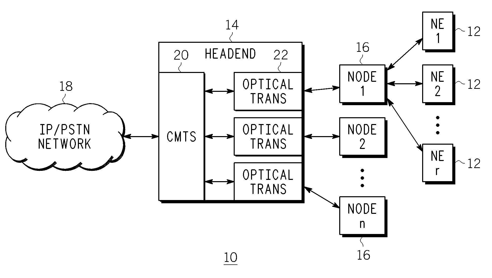
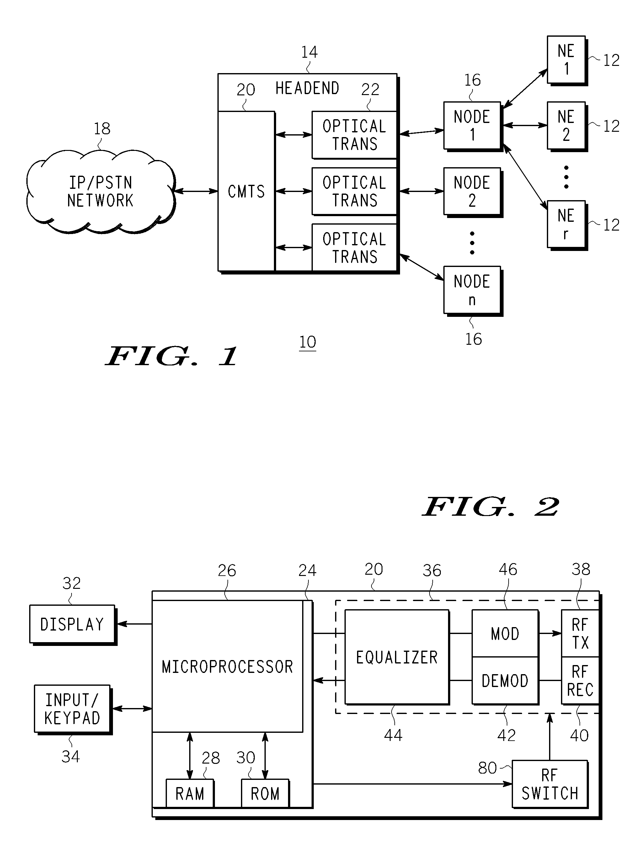
[0030]For this purpose and by way of example, FIG. 1 illustrates an exemplary network 10, such as an HFC network, including a plurality of end user terminal network elements 12, such as cable modems, set top boxes, televisions equipped with set top boxes, DOCSIS terminal devices, MTAs or any other like element. The terminal network elements 12 interconnect to a headend 14 of the network 10 via nodes 16 and one or more taps (not shown). In turn, the headend 14 interconnects to an IP (Internet Protocol) and / or PSTN (Public Switched Telephone Network) network 18.

[0031]As illustrated in FIG. 1, the headend 14 includes a cable modem termination system (CMTS) unit 20 and optical transceivers 22 which provide optical com...


PUM


Abstract

Methods are described for identifying a dominant impairment on a communication channel impaired by an interference issue. The methods include systematic examination of total power loading, systematic examination of signal power reduction, statistical examination of communication channel noise power, and systematic examination of interleaver effectiveness. Each relates to automatically diagnosing and characterizing distortion-based interference issues by monitoring the performance of a communication channel during a testing procedure. These methods enable a technician or engineer to remotely diagnose distortion-based interference issues relatively quickly without having to use external test equipment and without having to deploy technicians to various locations within the cable plant. A system by which these methods can be implemented is also disclosed.

Description

CROSS-REFERENCE TO RELATED APPLICATIONS[0001]This application is related to U.S. patent application Ser. No. ______ of Thompson et al. titled “Methods and System for Determining a Dominant Impairment of an Impaired Communication Channel” (Docket No. BCS05084) filed on Dec. 23, 2008.FIELD OF THE INVENTION[0002]Methods and a system for characterizing impairments on a communication channel of a network are disclosed, and more particularly, processes for monitoring the performance of a communication channel impaired with a noise and / or narrowband interference issue is provided in a manner permitting a dominant impairment to be identified.BACKGROUND OF THE INVENTION[0003]Hybrid fiber coaxial (HFC) cable television systems include a so-called headend which provides communications between end users in the HFC network and IP / PSTN networks. The headend typically contains a cable modem termination system (CMTS) containing several receivers, each receiver handling communications between hundre...

Claims


Application Information

Patent Timeline
IPC IPC(8): H04L12/26
CPCH04L12/2697H04L43/0823H04L43/50H04L43/10H04L43/0829
Inventor THOMPSON, ROBERT J.COOPER, MICHAEL J.MOORE, CHARLES S.MORAN, III, JOHN L.
Owner GOOGLE TECH HLDG LLC
Why Eureka
Try Eureka