
Packet transfer method, packet transfer device, and packet transfer system

a packet transfer and packet technology, applied in data switching networks, instruments, high-level techniques, etc., can solve the problems of inability to achieve power saving effect, etc., to achieve power saving effect, and extremely low load of packet transfer devi

Inactive Publication Date: 2010-06-24
ALAXALA NETWORKS
View PDF10 Cites 19 Cited by
  • Summary
  • Abstract
  • Description
  • Claims
  • Application Information

AI Technical Summary

Benefits of technology

[0010]One of objects of the present invention is to provide a packet transfer method capable of realizing lower power consumption of the network when the volume of packets circulating in the network (traffic volume) is small and the load of the packet transfer of the packet transfer devices that constitute the network is low. Moreover, the present invention has further one object to provide a packet transfer device that implements the packet transfer method.
[0017]According to the present invention, when the quantity of the packet (traffic volume) circulating in the network is small and the load of the packet transfer of the packet transfer devices that constitute the network is low, it becomes possible to reduce electric power consumed by the network. Moreover, according to the present invention, it becomes possible to provide the packet transfer device that implements the packet transfer method.

Problems solved by technology

Therefore, there is a case where a power saving effect cannot be attained.
Therefore, even in the case where the load of the packet transfer device is extremely low, all the interface ports need to be energized, and consequently there is a case where the power saving effect cannot be attained.
For this reason, a network that consists of the packet transfer devices as described in JP-A-Hei11 (1999)-088458 or 2 aiming at lower power consumption has a problem that lower power consumption is not realized even when the load of the packet transfer of the packet transfer device is low and a volume of packet circulating in the network is small.

Method used


Image

  • Packet transfer method, packet transfer device, and packet transfer system
  • Packet transfer method, packet transfer device, and packet transfer system
  • Packet transfer method, packet transfer device, and packet transfer system

Examples


Embodiment Construction

1. Network Configuration and Operation of Packet Transfer

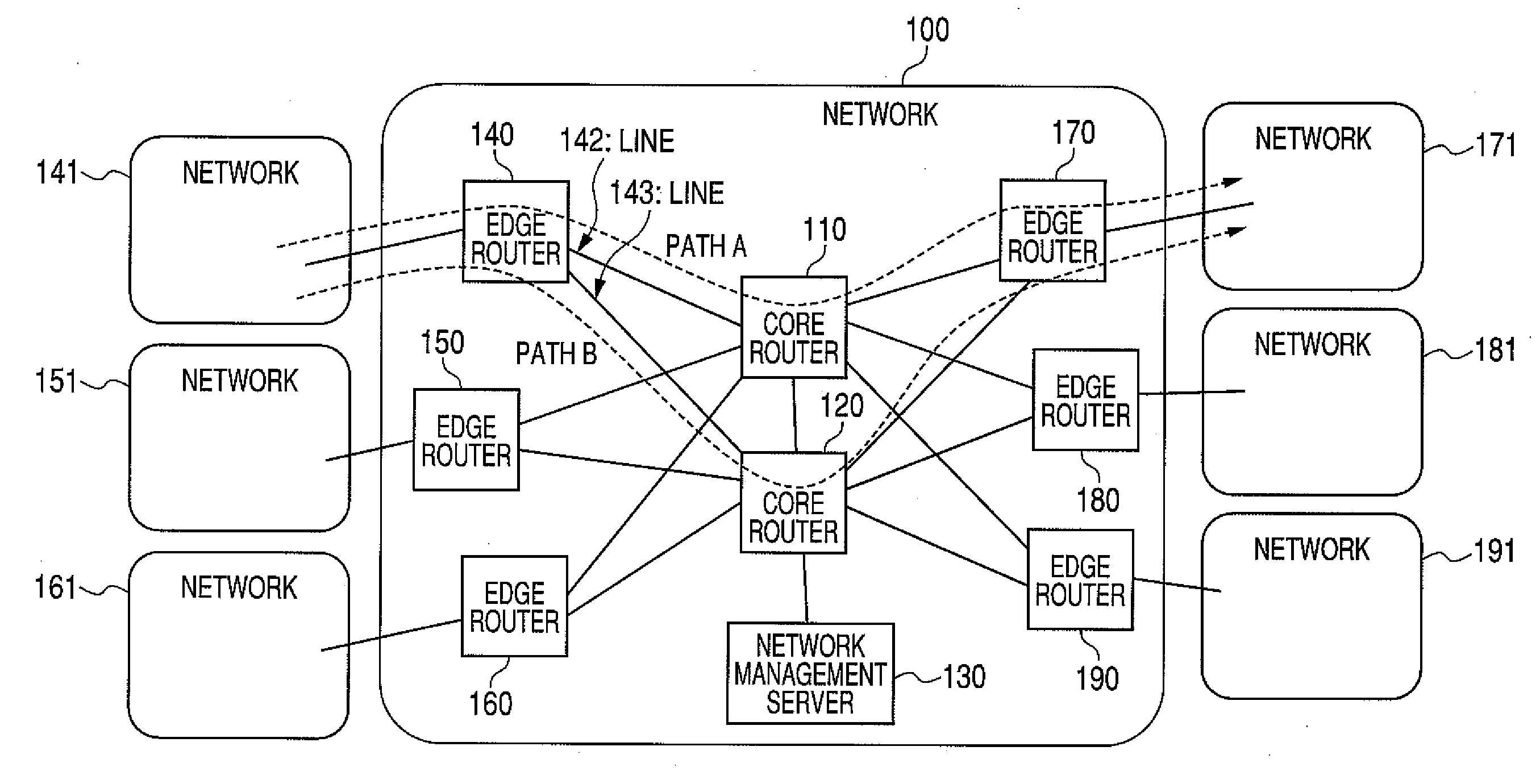
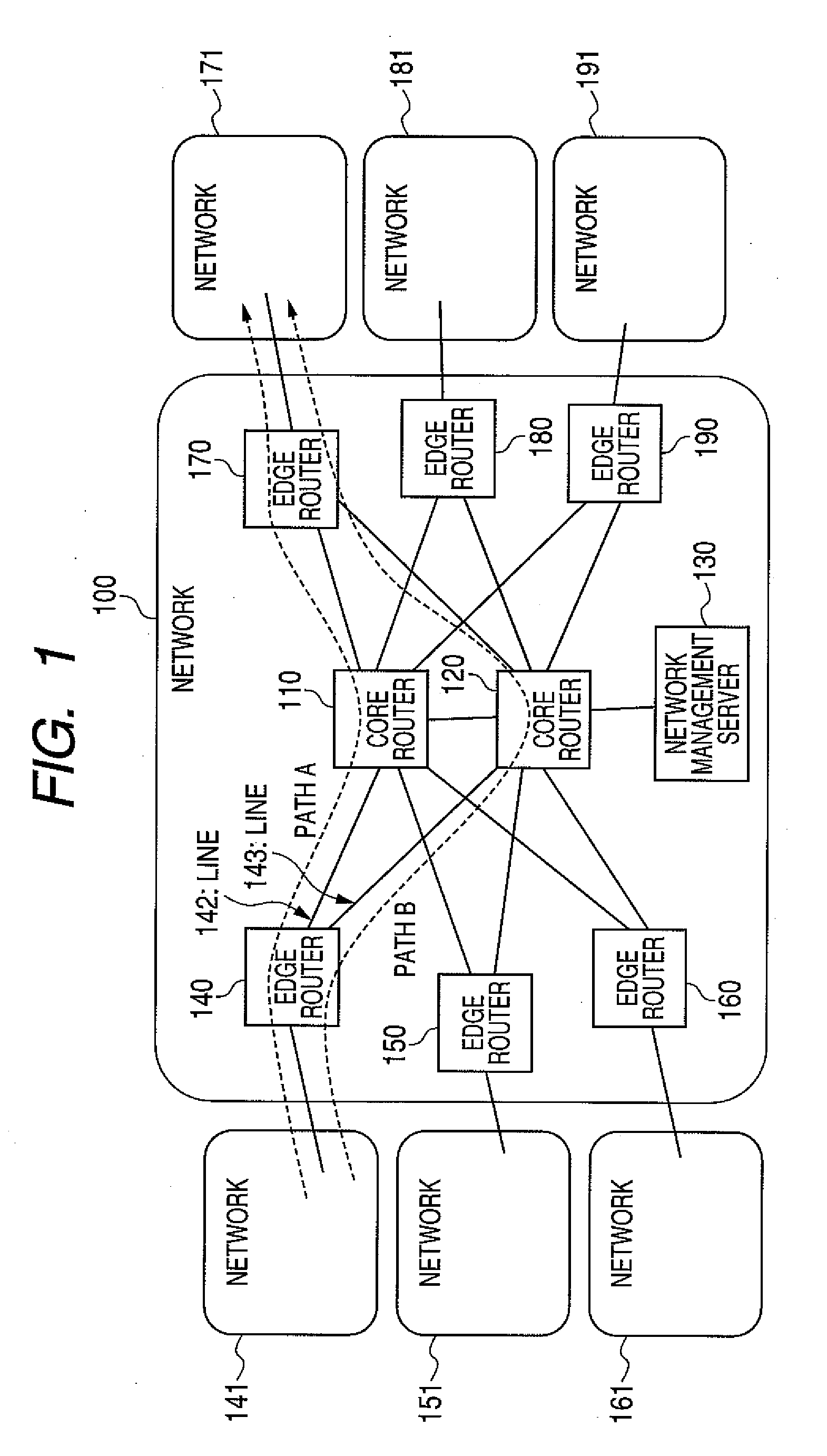
[0028]An operation of packet transfer in this embodiment will be explained using FIG. 1.

[0029]FIG. 1 shows a configuration diagram of a network 100 that this embodiment assumes and networks 141, 151, 161, 171, 181, and 191 linked by the network 100. The network 100 is equipped with, for example, plural edge routers 140, 150, 160, 170, 180, and 190 (in the example of illustration, six sets), plural core routers 110, 120 (in the example of illustration, two sets) that link together the edge routers with one another, and a network management server 130. For the each router, a path starting from each of the networks 141, 151, 161, 171, 181, and 191 and leading to other networks 141, 151, 161, 171, 181, and 191 via the edge router and the core router is set. FIG. 1 shows a path A starting from the network 141 and leading to the network 171 via the edge router 140, the core router 110, and the edge router 170, and a path B starting ...


PUM


Abstract

An edge router measures a traffic volume inputted into a network, and the measurement result is notified to a network management server. If the network management server judges that the notified traffic volume is “smaller” than a capacity of a second core router, it will direct a first core router to shift to a power saving mode. The first core router notifies the edge router of the shift to the power saving mode, and the edge router updates a routing table so that the packet to the first core router may be bypassed to the second core router. The first core router shifts to the power saving mode that does not perform packet transfer, and reduction in electric power is realized.

Description

CLAIM OF PRIORITY[0001]The present application claims priority from Japanese patent application JP 2008-325992 filed on Dec. 22, 2008, the content of which is hereby incorporated by reference into this application.FIELD OF THE INVENTION[0002]The present invention relates to a packet transfer method, a packet transfer device, and a packet transfer system and, more specifically, to a packet transfer method, a packet transfer device, and a packet transfer system in a network that transfers a packet in a power saving manner according to a traffic volume.BACKGROUND OF THE INVENTION[0003]Against the backdrop of the spread of the Internet, improvement in the speed of the packet transfer device, such as a router and a switch that constitute a network is being sought. Each of the router and the switch is equipped with plural input lines and output lines, determines the output line from a destination address in a header upon input of a packet from the input line (hereinafter, this processing ...

Claims


Application Information

Patent Timeline
Patent Type & Authority Applications(United States)
IPC IPC(8): H04L12/26H04L12/56G06F1/26H04L45/24H04L47/762
CPCG06F1/3209H04L12/12H04L41/0896Y02B60/34H04L45/00H04L45/04Y02B60/32H04L43/0882Y02D30/50
Inventor YAZAKI, TAKEKIOKU, TOMOYUKINAGASAKA, MITSURU
Owner ALAXALA NETWORKS
Learn More