Base Station Device, Method for Controlling Base Station Device, Receiving Device, Adaptation Algorithm Control Method, Radio Communication Device, and Radio Communication Method

Inactive Publication Date: 2010-06-24
KYOCERA CORP
View PDF7 Cites 21 Cited by
  • Summary
  • Abstract
  • Description
  • Claims
  • Application Information

AI Technical Summary

Benefits of technology

[0041]This enables weighting of transmitting signals and/or received signals in a part of communication channels that have less interference noise of the multiple communication channels related to diversity communications by using the gain prioritized algorithm, and weighting of signals in other communication channels by using an interference suppression prioritized algorithm, respectively. Consequently, a signal having better communication characteristics can be selected from the signals that are transmitting signals and/or received signals containing the same data, respectively, weighted by using the gain prioritized algorithm and the interference suppression prioritized algorithm that are in a trade-off relationship.
[0042]In addition, in the above radio c

Problems solved by technology

However, the weight calculation algorithms described above have the following problem.
To be specific, when a difference in reception power among reference signals transmitted by multiple mobile station devices, which are targets for multiplexing communications, is large, a base station device cannot suitably calculate weight of each antenna element of an array antenna.
For example, when directing a beam to the arriving direction of a first reference signal of high radio field strength, a base station device has difficulty in appropriately directing a null to the arriving direction of a second reference signal that has relatively lower reception power than the first reference signal, that is, has low correlation with the first reference signal.
In this case, quality of communications between the base station device and a mobile station device transmitting the second reference signal deteriorates due to influence of communications with a mobile station device transmitting the first reference signal.
Further, the adaptation algorithms described above have the fo

Method used


Image

  • Base Station Device, Method for Controlling Base Station Device, Receiving Device, Adaptation Algorithm Control Method, Radio Communication Device, and Radio Communication Method
  • Base Station Device, Method for Controlling Base Station Device, Receiving Device, Adaptation Algorithm Control Method, Radio Communication Device, and Radio Communication Method
  • Base Station Device, Method for Controlling Base Station Device, Receiving Device, Adaptation Algorithm Control Method, Radio Communication Device, and Radio Communication Method

Examples


first embodiment

[0058]A first embodiment of the present invention will be described below on the basis of the drawings.

(Overall Configuration of Mobile Communication System)

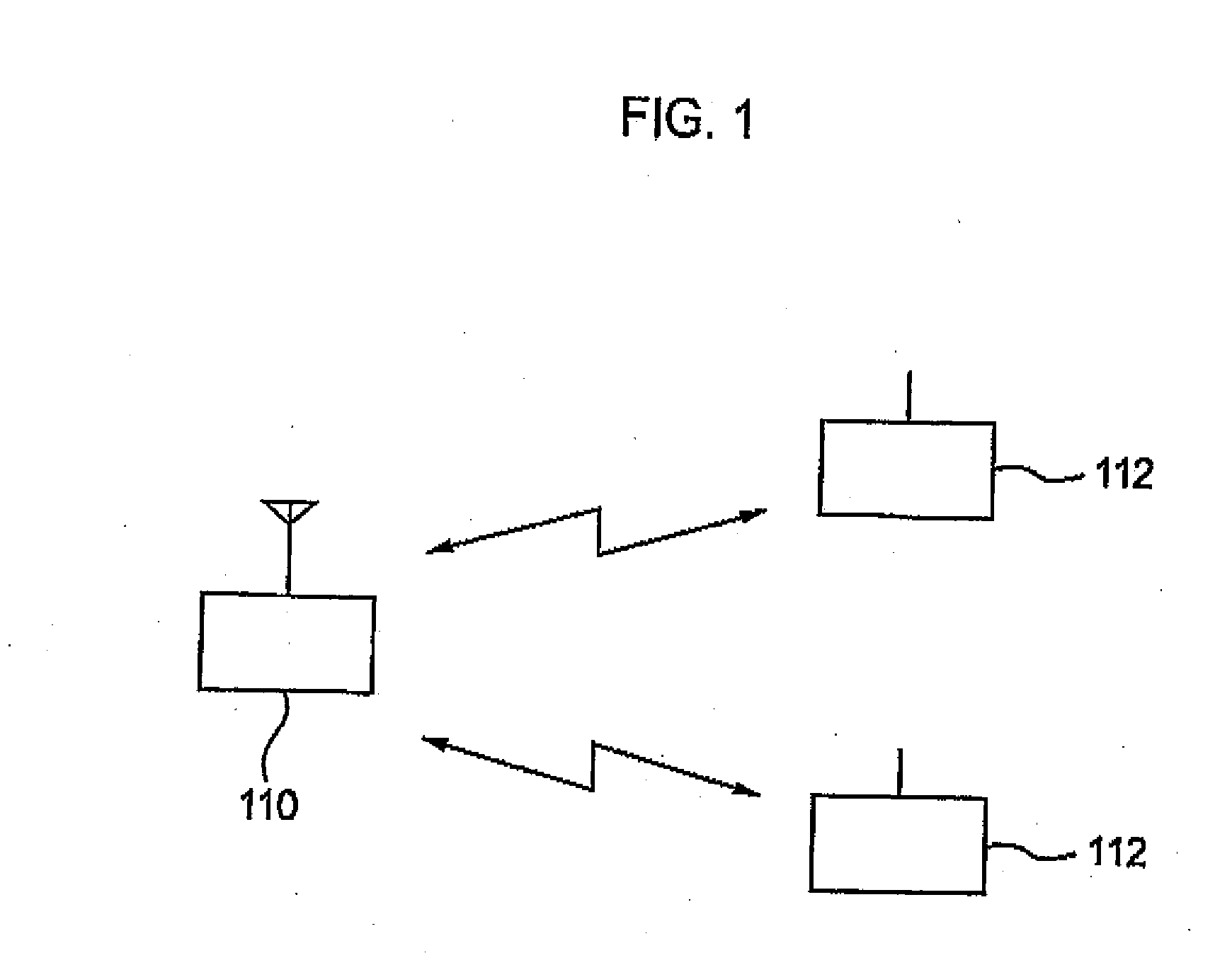
[0059]FIG. 1 is an overall configuration diagram of a mobile communication system according to a first embodiment of the present invention. As shown in FIG. 1, the mobile communication system includes a base station device 110 and multiple mobile station devices 112 (2 in this embodiment). Each of the mobile station devices 112 is a portable phone or a data terminal, for example, and wirelessly communicates with the base station device 110. Here, the base station device 110 and each of the mobile station devices 112 transmit and receive data by using the TDD (Time Divisional Duplication) scheme and perform multiplex communications by using the TDMA (Time Division Multiple Access) scheme.

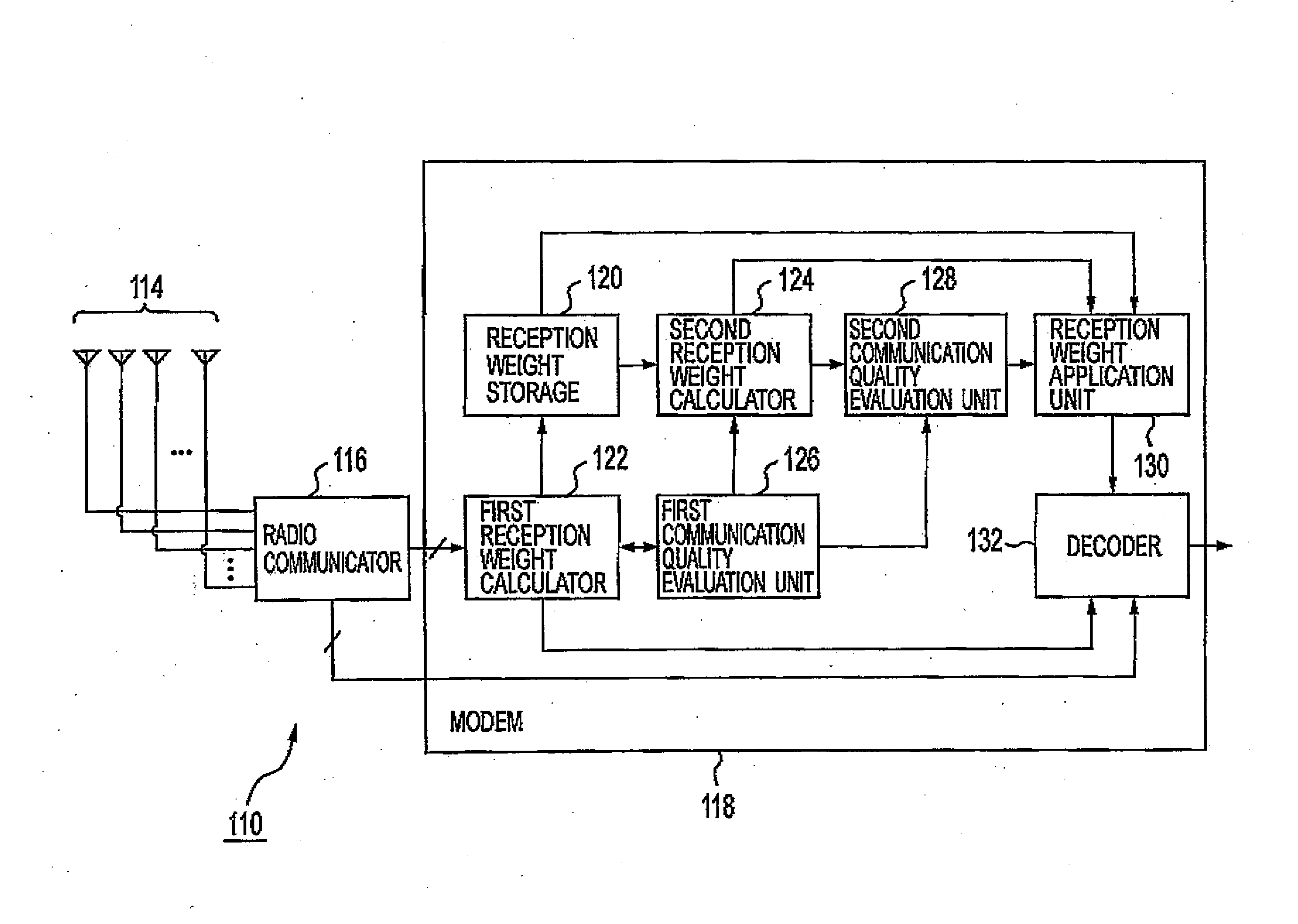
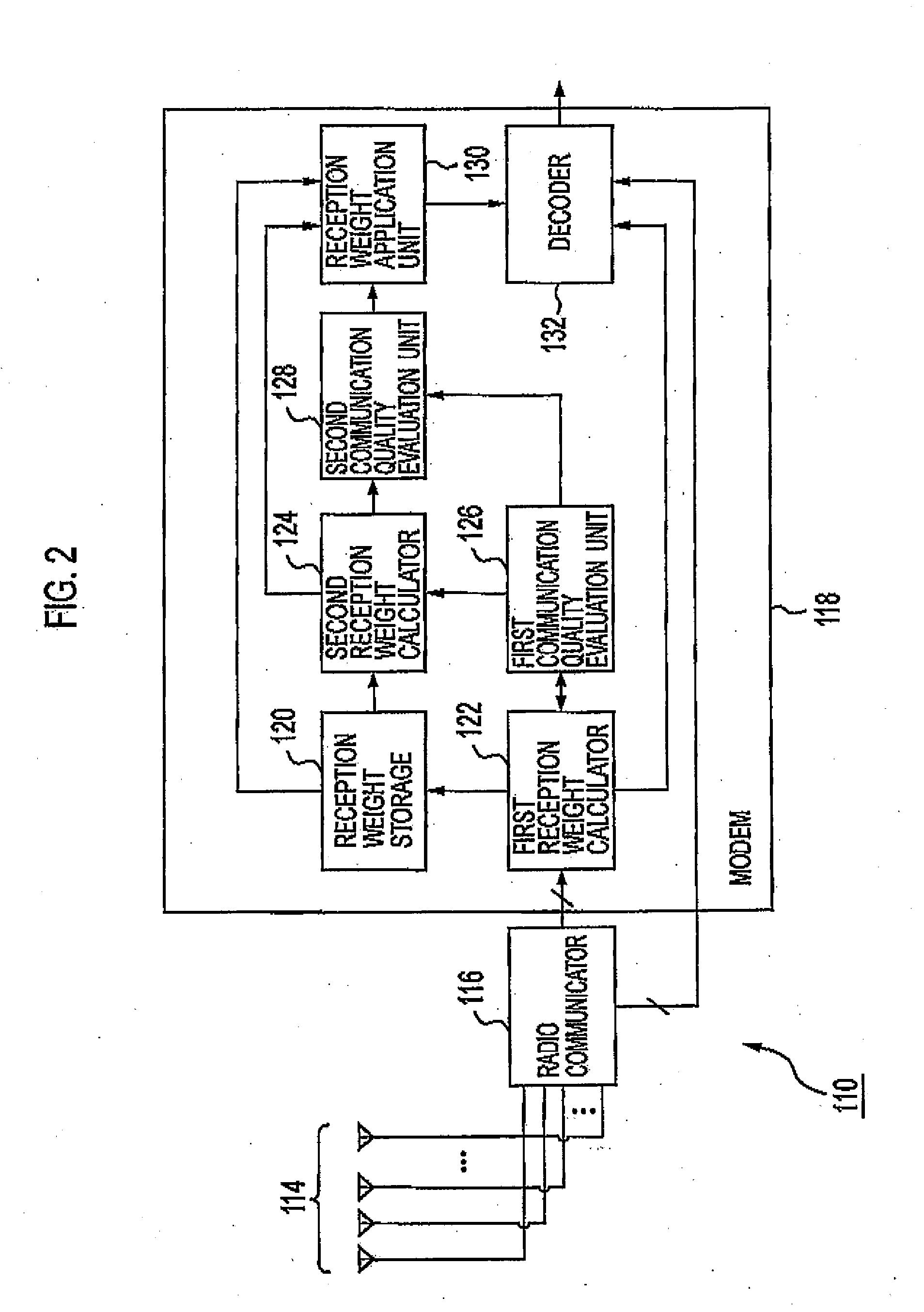
[0060]Further, the base station device 110 includes array antennas as described below, and performs multiplex communications with each of the mo...

second embodiment

[0085]Next, a second embodiment of the present invention will be described with reference to the drawings.

(Configuration of Receiving Device)

[0086]FIG. 5 is a block diagram showing a system configuration and functional blocks of a receiving device 201a according to a second embodiment of this implementation. As shown in FIG. 5, the receiving device 201a includes an adaptive controller 202a. The adaptive controller 202a includes ah array antenna formed of 4 antenna elements 210 (antenna element 210-0, 210-1, 210-2, 210-3). Further, the adaptive controller 202a also includes multipliers 211 (multiplier 211-0, 211-1, 211-2, 211-3) for the respective antenna elements 210.

[0087]Further, the adaptive controller 202a includes: a synthesizer 212, a synthesizer 213, a used adaptation algorithm changing unit 214, a PI controller 216, an MMSE controller 217, a desired wave power information acquisition unit 218, and an undesired wave power information acquisition unit 219. Furthermore, the use...

first modification

of Second Embodiment

[0112]Next, a first modification of the second embodiment of the present invention will be described with reference to the drawings.

[0113]FIG. 6 is a block diagram showing a system configuration and functional blocks of a receiving device 201b according to the first modification of the second embodiment of the present invention. As shown in FIG. 6, the receiving device 201b includes an adaptive controller 202b instead of the adaptive controller 202a. The adaptive controller 202b separates the multiplier 211-0 and the multiplier 211-1 in the above-described adaptive controller 202a into a multiplier 211-4 and a multiplier 211-6, and into a multiplier 211-5 and a multiplier 211-7, respectively. In the adaptive controller 202b, the MMSE controller 217 refers to a receiving wave after the PI controller 216 multiplies reception weight.

[0114]This enables the adaptive controller 202b to perform adaptive control by both PI and MMSE at all times. Thus, as in the second em...


PUM


Abstract

A base station device according to the present invention includes: a first reception weight calculator 122 configured to calculate weight, of each antenna element of an array antenna 114 to be used in communications with a first mobile station device by using a reference signal transmitted from the first mobile station device; and a second reception weight calculator 124 configured to calculate weight of each antenna element of the array antenna 114 to be used in communications with a second mobile station device, which is different from, the first mobile station device of the multiple mobile station devices, the second reception weight calculator 124 calculating the weight so that null can be directed to an arriving direction of the reference signal transmitted from the first mobile station device, the arriving direction being determined on the basis of weight calculated by the first reception weight calculator 122.

Description

TECHNICAL FIELD[0001]The present invention relates to an adaptive array technology using an array antenna formed of multiple antenna elements. Particularly, the present invention relates to a base station device to which the adaptive array technology is applied, a method for controlling the base station device, a receiving device, an adaptation algorithm control method, a radio communication device, and a radio communication method.BACKGROUND ART[0002]According to the adaptive array technology, a beam can be directed to a user of a desired wave (beam forming) and a null can be directed to a user of an interference wave (null steering), by appropriately setting weight of each antenna element of an array antenna.[0003]Space-Division Multiple Access (SDMA) scheme has been known, as a multiplexing scheme that utilizes the adaptive array technology. In a mobile communication system that employs the SDMA, a base station device can communicate with each of multiple mobile station devices s...

Claims


Application Information

Patent Timeline
IPC IPC(8): H04W72/04H04B1/06
CPCH04B7/0851
Inventor MIURA, TAKANORIHARA, TAKEHIROSAHARA, TORU
Owner KYOCERA CORP
Why Eureka
Try Eureka