Mounting Means For Mounting A Device With A Rotor

a technology of mounting means and rotors, which is applied in the direction of centrifuges, shafts and bearings, rotary bearings, etc., can solve the problems of increasing the limit speed which may not be exceeded, being effectively damped by oscillations, and being much more difficult to excite the mounting means

Active Publication Date: 2010-06-24
THERMO ELECTRONICS LED GMBH
View PDF14 Cites 2 Cited by
  • Summary
  • Abstract
  • Description
  • Claims
  • Application Information

AI Technical Summary

Benefits of technology

[0018]On the other hand, the mounting means can also comprise a plurality of mounting elements arranged non-symmetrically in relation to an axis of rotation of the rotor of the device mounted on the mounting means. In a mounting means of this type, a desired directional dependence of the resilient properties may easily be formed by arranging the mounting elements accordingly. In this case, at least two of the mounting elements can be arranged adjacently.
[0019]For example, in a mounting means with rotationally symmetrically arranged mounting elements all having the same modulus of elasticity, it is easy to provide a further mounting element which has just such a modulus of elasticity and is arranged adjacently to one of the mounting elements, wherein the two adjacent mounting elements can be arranged touching each other or without touching each other.

Problems solved by technology

This makes it much more difficult to excite the mounting means to form unstable oscillations, so that such oscillations are effectively damped.
This leads to an increase in the limit speed which may not be exceeded in order for the device to run stably, wherein expensive and high-wearing damping elements, such as viscous dampers, friction dampers, etc., may be dispensed with.
Such cases usually occur in relatively complex rotor designs such as what are known as “biodense” rotors, which consist of a large number of interconnected individual components, or on use of self-locking shaft / hub couplings.

Method used


Image

  • Mounting Means For Mounting A Device With A Rotor
  • Mounting Means For Mounting A Device With A Rotor
  • Mounting Means For Mounting A Device With A Rotor

Examples


Embodiment Construction

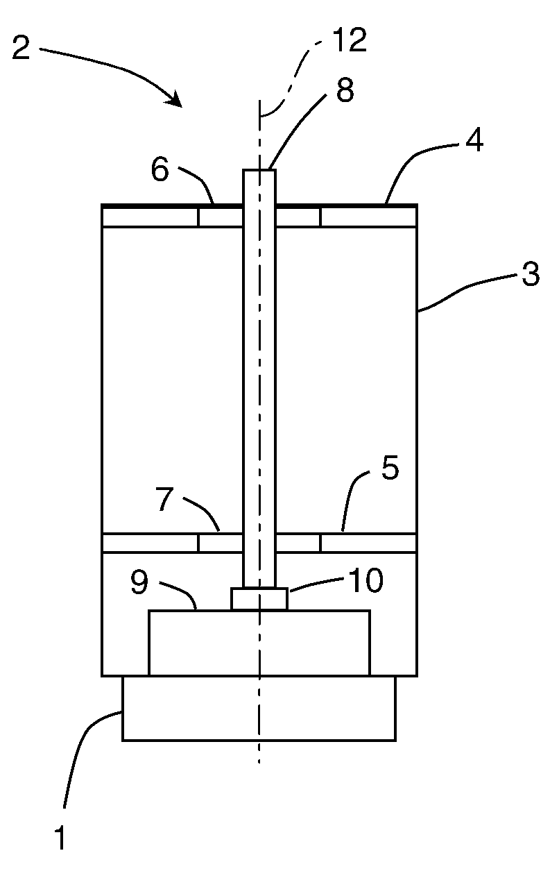
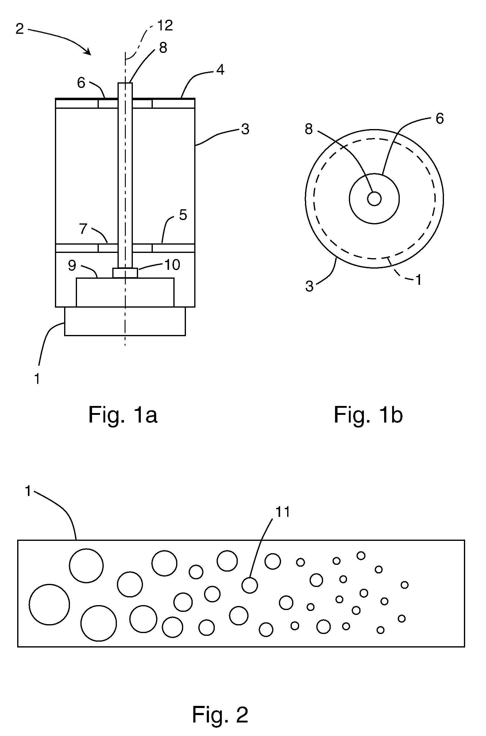
[0036]Referring now to the figures, FIG. 1a is a schematic cross section through an arrangement, which is illustrated in highly simplified form, with a mounting means 1 made of a rubber material according to a first embodiment and a device 2 mounted thereon. FIG. 1b is a plan view of the arrangement from FIG. 1a. The device 2 comprises a substantially cylindrical housing 3, an upper mounting shield 4 arranged in the housing 3 and a lower mounting shield 5, a pivot bearing 6 arranged in the upper mounting shield 4 and a pivot bearing 7 arranged in the lower mounting shield 5, and also a shaft 8, which is mounted in the pivot bearings 6 and 7 so as to be able to rotate about an axis of rotation 12, as the rotor. Furthermore, the device 2 comprises, as the drive for the shaft 8, a motor 9 which is also arranged in the housing 3 and connected to the shaft 8 via a shaft / hub coupling 10.

[0037]In the present case, sliding bearings are provided for both pivot bearings 6 and 7. Alternatively...


PUM


Abstract

A mounting means is provided for mounting a device comprising at least one mounting shield, a pivot bearing arranged in the mounting shield and a rotor mounted perpendicularly in the pivot bearing, an axis of rotation of the rotor being oriented substantially perpendicularly when the device is mounted on the mounting means, and the mounting means having resilient properties. In one embodiment, the resilient properties of the mounting means are direction-dependent, in particular orthotropic. As a consequence of the direction-dependent resilient properties of the mounting means, oscillations excited by a rotary movement of the rotor strike a mounting, the pivot point of which does not coincide with the axis of rotation of the rotor, but is set apart therefrom. This makes it much more difficult to excite the mounting means to form unstable oscillations, so that such oscillations are effectively damped.

Description

RELATED APPLICATION[0001]The present application claims the priority under 35 U.S.C. §119 of German Patent Application No. 102008063632.0, filed Dec. 18, 2008, the disclosure of which is hereby incorporated herein by reference in its entirety.FIELD OF THE INVENTION[0002]The present invention relates to a mounting means for mounting a device comprising at least one mounting shield, a pivot bearing arranged in the mounting shield and also a rotor mounted in the pivot bearing, an axis of rotation of the rotor being oriented substantially perpendicularly when the device is mounted on the mounting means, and the mounting means having resilient properties. For example, the mounting means can be provided for mounting a motor, which has rotatably mounted elements such as for example a shaft, or a centrifuge.BACKGROUND OF THE INVENTION[0003]In real devices with rotating rotors, mass distributions which are not completely rotationally symmetrical give rise to centrifugal and bearing forces wh...

Claims


Application Information

Patent Timeline
Patent Type & Authority Applications(United States)
IPC IPC(8): B04B9/08F16C27/00F16C27/06
CPCF16F15/04F16C2300/34
Inventor HENNE, SEBASTIAN
Owner THERMO ELECTRONICS LED GMBH
Why Eureka
Try Eureka