Drill guide with angle verification

a technology of angle verification and drill guide, which is applied in the field of angle verification, can solve the problems of bone deformation, difficult to drill the pilot hole at the correct angle, and surgeons often had difficulty eyeing the correct angl

Inactive Publication Date: 2010-06-24
HOWMEDICA OSTEONICS CORP
View PDF12 Cites 49 Cited by
  • Summary
  • Abstract
  • Description
  • Claims
  • Application Information

AI Technical Summary

Benefits of technology

[0007]The visual reference may be a reduction in diameter, a protrusion, an etched line or a laser marked line. Also color and surface finish could be used as visual indicators. Additionally, two or three visual references could be used indicating different angle markings i.e. 5°, 10° or 15°. Thus two or three lines could be used at different levels with the lower line corresponding to the greater angle. The visual reference may be observed by the surgeon and indicates to him that the pilot hole an

Problems solved by technology

If the bone screw is put in at too great an angle the bone screw head would sit proud of the bone plate which in some situations is undesirable.
The surgeon often had difficulty eyeing the correct angle especially where there was a plurality of bone screws to be inserted, since the correct angle is relatively small i.e. zero to ten degrees.
Normally, the surgeon drills a pilot hole in the bone prior to inserting the bone screw and it has been difficult to drill the pilot hole at the correct angle so that the bone screw would seat properly.
Consequently, if the pilot hole and subsequent bone screw are inserted at an incorrect angle the head of the bone screw could impinge on the distal surface of the polyethylene bearing implant which is undesirable.
Suc

Method used


Image

  • Drill guide with angle verification
  • Drill guide with angle verification
  • Drill guide with angle verification

Examples


Embodiment Construction

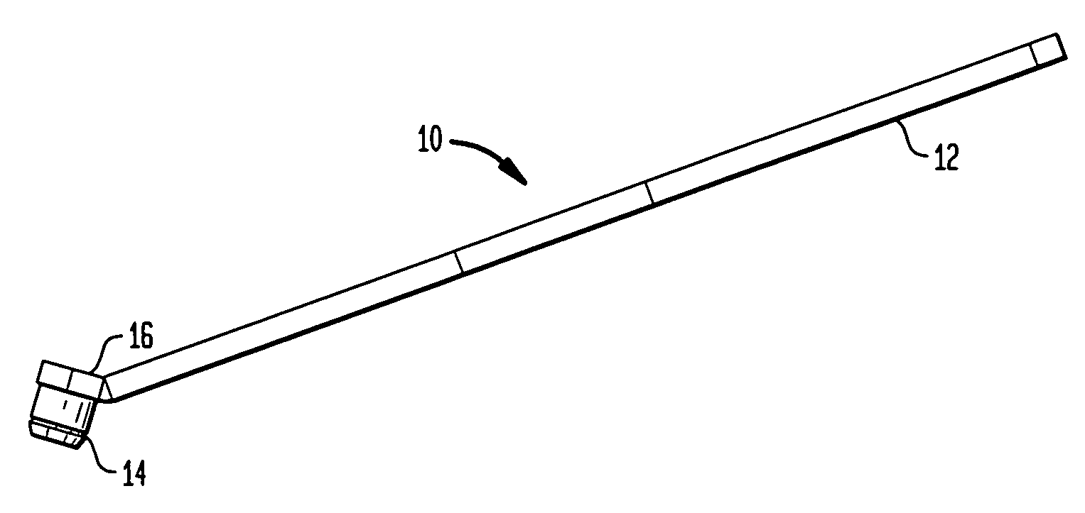
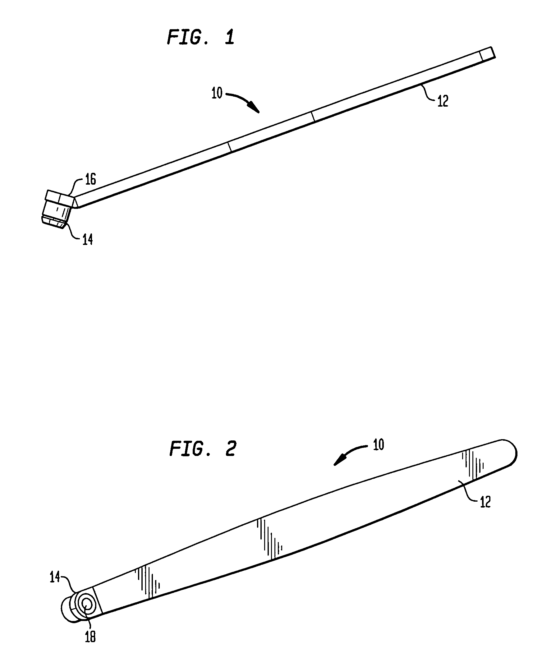
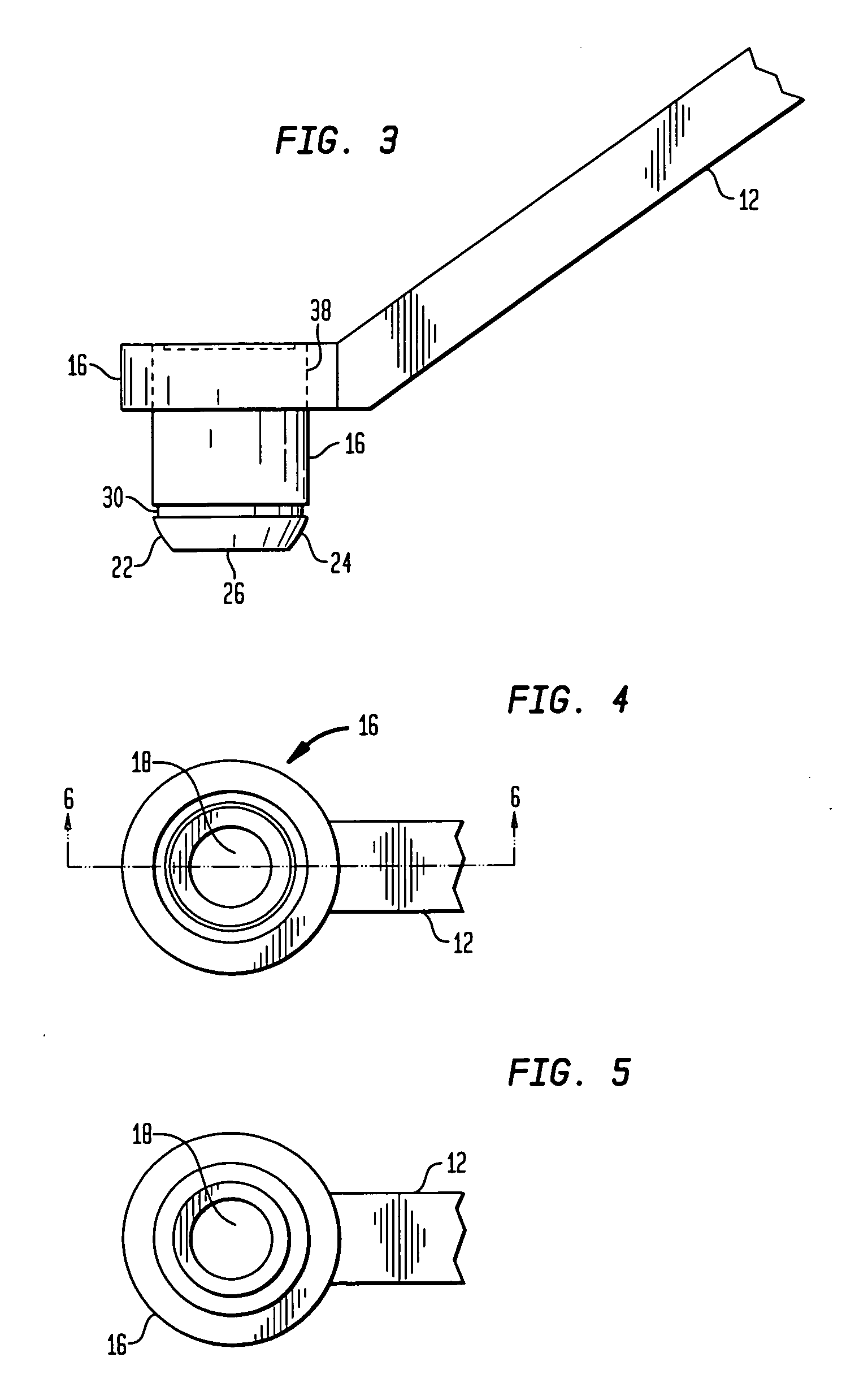
[0026]Referring to FIG. 1, there is shown an isometric view of the instrument of the present invention generally denoted as 10. Instrument 10 includes a handle portion 12 and a leading or distal end 14 which includes a drill guide element 16 as can be seen in FIGS. 2, 4 and 5. Drill guide element 16 includes a guide bore 18. Guide bore 18 is adapted to receive a drill bit 20 such as shown in FIG. 9.

[0027]Referring to FIG. 3, the drill guide element 16 has a leading end 22 which, in the preferred embodiment is cylindrical and includes a part-spherical convex contact surface 24 for engaging a part-spherical concave surface 28 surrounding a plate bore as shown in FIGS. 8 and 9. In the preferred embodiment, the element 16 includes a marking ring or line 30 which can be etched or laser marked or even being a groove of a reduced diameter in a predetermined axial location along the axial direction of element 16. The spacing of marking 30 with regard to end 26 of element 16 is determined by...


PUM


Abstract

A method and instrument is used for inserting a bone screw into a hole in a bone plate and into bone at a maximum angulation of a bone screw central longitudinal axis with respect to a central axis of the hole. The maximum angulation is that which places the head of the bone screw at or below an outwardly facing surface of the bone plate. The instrument has a distal end including a gauge element, spaced proximally from an end surface of the distal end when in contact with a counterbore surrounding the plate hole. The space is less than or equal to a distance from the counterbore surface to the outwardly facing surface of the bone plate. The instrument is tilted with respect to a central axis of the bone plate hole to an angle wherein the gauge element remains at or below the outwardly facing surface of the bone plate adjacent the counterbore. A hole is drilled in the bone through a guide bore in the instrument.

Description

BACKGROUND OF THE INVENTION[0001]The invention relates to an angle guide for orienting a bone screw in a bone plate. More particularly, the invention relates to an instrument for insuring the position of the head of a bone screw located within a bone plate hole.[0002]It is often necessary when utilizing bone plates either for fracture fixation or such as tibial base plates to couple the bone plates to bone via a screw extending through a hole in the plate. When the screw is angled, surgeons have had to eye the correct angle specified by the device manufacturer indicated by the surgical situation. If the bone screw is put in at too great an angle the bone screw head would sit proud of the bone plate which in some situations is undesirable. The surgeon would then either continue to torque the bone screw until the bone screw's cutting flutes soften the bone in the area and allowed it to sit properly or the bone screw would be backed out and the surgeon would attempt to reinsert the bon...

Claims


Application Information

Patent Timeline
IPC IPC(8): A61B17/58
CPCA61B17/1728A61B17/1739A61B2019/467A61B2090/067
Inventor SOLIMAN, MOHAMED
Owner HOWMEDICA OSTEONICS CORP
Why Eureka
Try Eureka