Bone screw assembly with non-uniform material

a non-uniform material and screw technology, applied in the field of bone anchors, can solve problems such as the dislocation of the rod from the spinal fixation devi

Inactive Publication Date: 2010-06-24
K2M
View PDF83 Cites 44 Cited by
  • Summary
  • Abstract
  • Description
  • Claims
  • Application Information

AI Technical Summary

Problems solved by technology

These rods provide the needed strength to correct the deformity, but due to the strength of typical spine ...

Method used


Image

  • Bone screw assembly with non-uniform material
  • Bone screw assembly with non-uniform material
  • Bone screw assembly with non-uniform material

Examples


Embodiment Construction

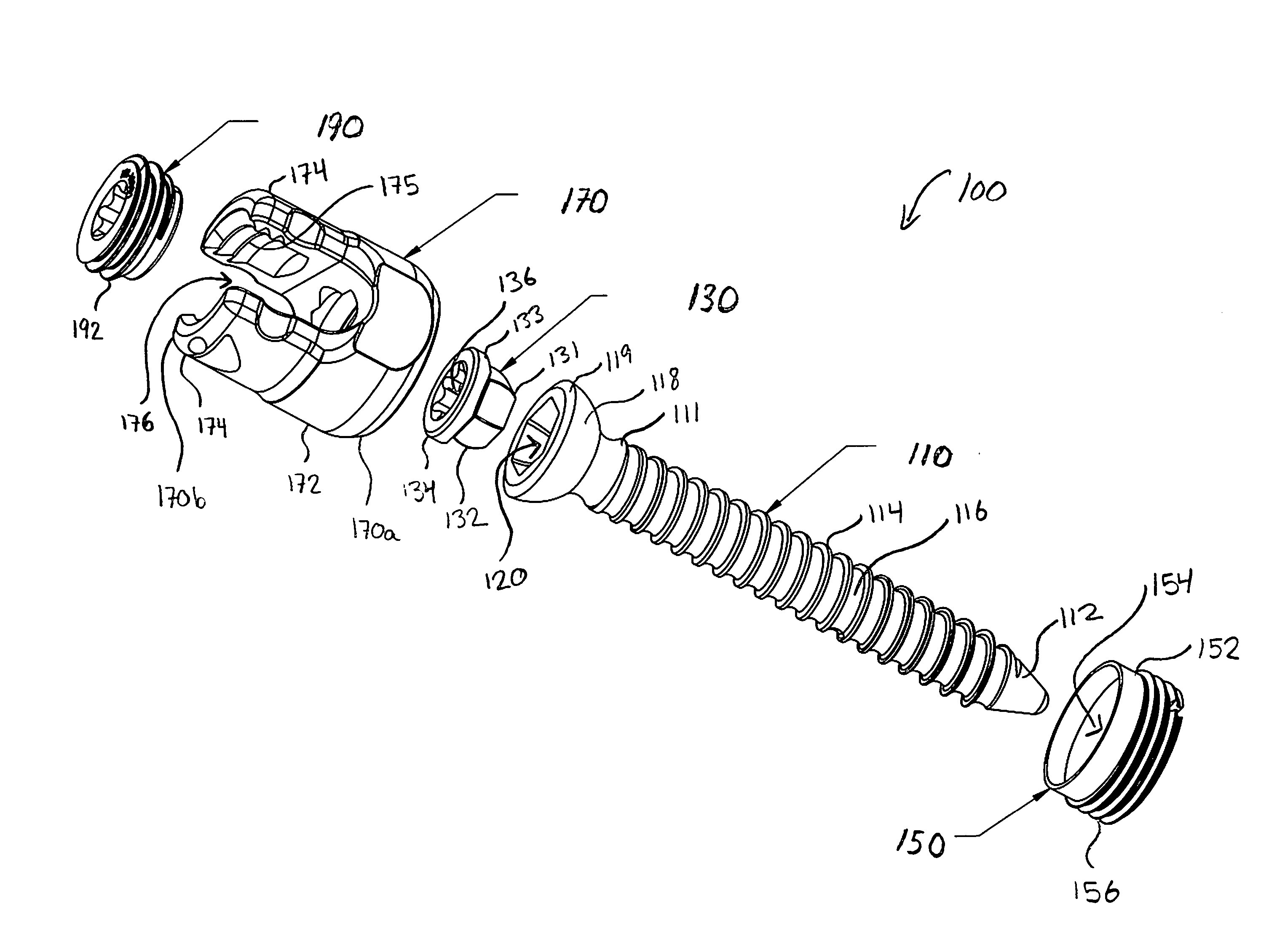
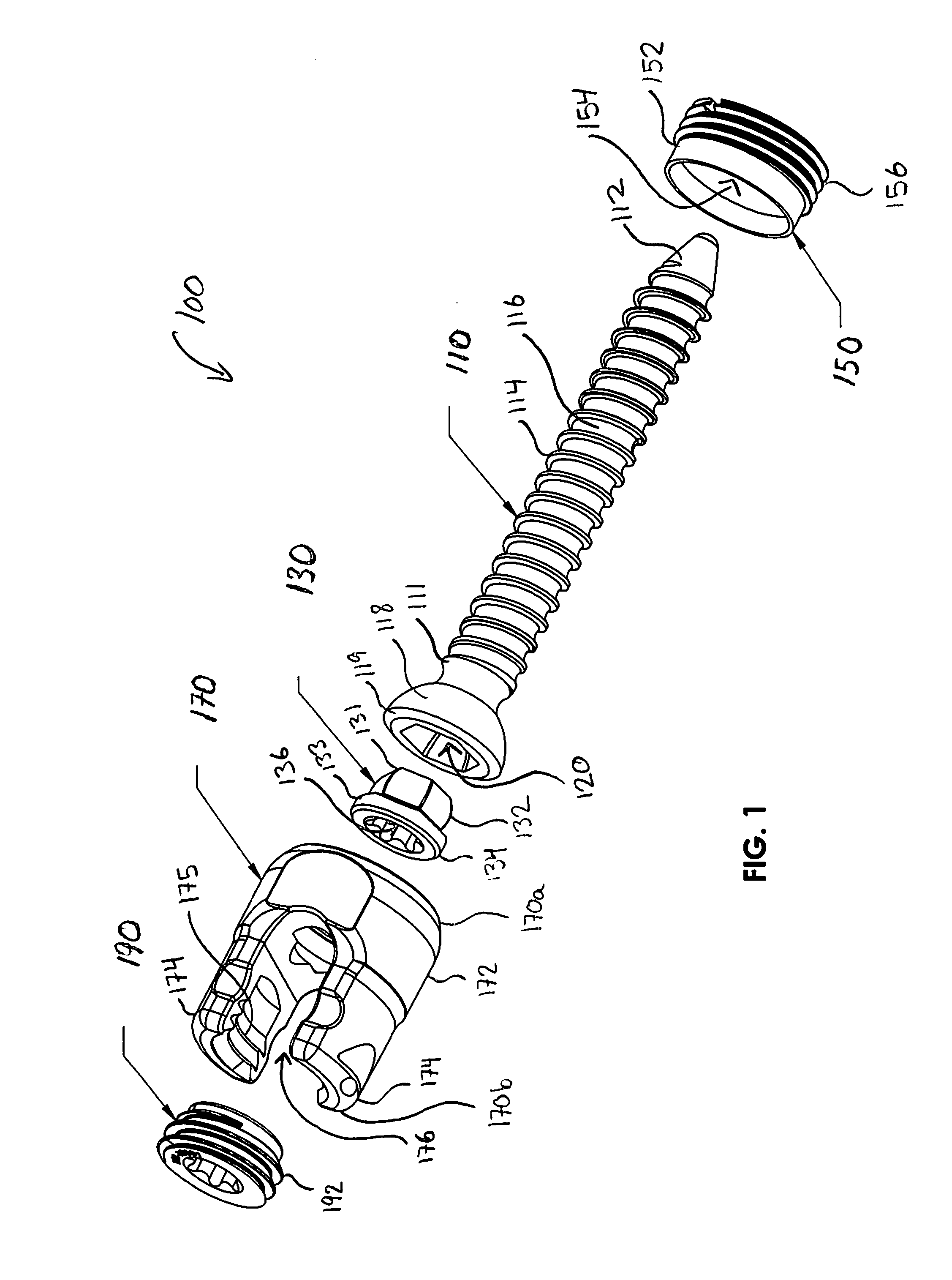
[0019]Turning to FIG. 1, a bone anchor 100 is shown including a pedicle screw 110, a coupling 130, an insert 150, a housing 170, and a locking element 190. During assembly of the bone anchor 100, the coupling 130 is positioned at a proximal end 111 of the pedicle screw 110 and the housing 170 is positioned over the coupling 130 and pedicle screw 110. The insert 150 is then passed over the distal end 112 of the pedicle screw 110 and is translated distally along the shaft 116 of the screw 110 towards the housing 170. The insert 150 is then engaged with a distal end 170a of the housing 170 to hold the bone anchor 100 together. The locking element 190 may then be engaged with a proximal portion 170b of the housing 170 to lock the screw 110 in place. Alternatively, the screw may be a top loading screw, such that an insert would not be required. In such an embodiment, the screw would first be inserted through the housing. The housing would be configured such that the head of the screw is ...


PUM


Abstract

A bone anchor comprises a screw having a threaded shank portion and a head portion, and a housing assembly. At least the threaded shank portion is formed from a titanium or titanium alloy and at least a portion of the housing is formed from a stronger material such as cobalt chrome. The housing assembly has a passageway extending therethrough and a proximal end and a distal end. A saddle is defined within the proximal end of the housing assembly and is configured to retain a portion of a rod therein. The distal end of the housing assembly is configured for securely engaging the head portion of the screw such that the screw is at least one of rotatable and pivotable with respect to the housing.

Description

CROSS-REFERENCE TO RELATED APPLICATIONS[0001]This application claims the benefit of and priority to U.S. Provisional Application Nos. 61 / 203,481 and 61 / 203,502, both of which were filed on Dec. 23, 2008, and are hereby incorporated by reference herein.BACKGROUND[0002]1. Technical Field[0003]The present disclosure relates to bone anchors and, more particularly, to pedicle screw assemblies made from non-uniform materials.[0004]2. Background of Related Art[0005]It is a common surgical procedure to stabilize and fix bones and bone fragments in a particular spatial relationship with fixation devices to correct the location of skeletal components due to injury or disease. This can be accomplished by using a number of fixation devices such as bone pins, anchors, or screws placed in bone across a discontinuity (e.g., a fracture) in the bone, bone fragments, adjacent vertebrae, or joints. These fixation devices can be connected by a rod to maintain a desired spatial relationship. In some cas...

Claims


Application Information

Patent Timeline
IPC IPC(8): A61B17/86
CPCA61B17/866A61B17/7037
Inventor CARBONE, JOHN
Owner K2M
Why Eureka
Try Eureka