Endovascular graft device and methods for attaching components thereof

a technology of endovascular graft and components, applied in the field of endovascular graft assembly, can solve the problems of life-threatening, significant life-threatening or significant morbidity of surgical repair, and achieve the effect of reducing the delivery profile, facilitating accurate catheterization and deployment of limb components, and adding bulk to the gra

Inactive Publication Date: 2010-06-24
LIFEPORT SCI
View PDF18 Cites 54 Cited by
  • Summary
  • Abstract
  • Description
  • Claims
  • Application Information

AI Technical Summary

Benefits of technology

[0017]In one aspect, the invention is a main body component of a modular endovascular graft with an attachment frame, for example, a self-expanding attachment stent at its proximal end that is secured to the neck portion of the main body graft by hanging attachment arms, a stabilized trunk portion that resists twisting, and limb support portions that facilitate accurate catheterization and deployment of the limb components. Axial separation of the attachment stent from the main body graft of a modular endovascular graft allows anchoring the attachment stent above the renal arteries without disturbing blood flow into the renal arteries from the aorta and facilitates a reduced delivery profile since the stent and graft do not occupy the same axial location when compressed in the delivery system. By using hooks or a combination of stent eyelets and short sutures which connect the stent hanging attachment rings to the main body graft by engaging reinforced holes at the proximal end of the neck portion, the delivery profile is further reduced by avoiding suture knots which can add bulk to the graft in the delivery system. Another advantage of knot-less attachments is a reduction in the possibility of suture fatigue failures over the life of the graft. The delivery profile can be further reduced by eliminating unnecessary graft material between the reinforced holes at the proximal end of the neck portion, a process known as “scalloping”. Varying the length of the stent hanging connection rings and their associated connection hooks or sutures further reduces the delivery profile by limiting the number of hooks or eyelets which occupy the same axial location when the stent is compressed in the delivery system. Eyelets at the proximal end of the attachment stent facilitate its compression and loading into the loading capsule of the preferred embodiment delivery system.
[0018]If there is sufficient healthy tissue, additional self-expanding stents can be located at the proximal end of the neck portion and the distal end of each limb support portion. In order to minimize the delivery system profile, these stents can be delivered separately from the main body component. Stability of the main body component can be enhanced by a “U-shaped” wire in the main body graft which resists twisting.
[0019]Catheterization of the limb support portions of the main body component and accurate deployment of the limb components is facilitated by several features. Additional self-expanding attachment or support stents can be added to stabilize the main body component and hold the limb support portions open. These stents impact the delivery profile less than a full main body graft support stent and the impact can be minimized by making the limb support portions different lengths so their stents do not occupy the same axial location when the main body component is compressed in the delivery catheter. Furthermore, the limb support portions may be sutured together from the crotch to the distal end of the shortest limb support portion to resist twisting. Moreover, the catheterization of the limb support portion and delivery and deployment of the limb component to the contra-lateral side can be further facilitated by adding a bell-bottom endovascular graft section to the distal end of the contra-lateral limb support portion. By extending the bell-bottom stent longitudinally into the contra-lateral limb support section, a sufficient docking portion can be provided even if the bell-bottom endovascular graft becomes bent due to the configuration of the vasculature. By making the perpendicular profile of the distal end of the bell-bottom endovascular graft oval with respect to the body and the distal edge nearest the aneurysm wall significantly longer than the inner distal edge, the landing surface area can be increased further.

Problems solved by technology

For example, various types of aneurysms or other deteriorative diseases may affect the ability of the lumen to conduct fluids and, in turn, may be life threatening.
For repair of vital lumens such as the aorta, surgical repair is significantly life threatening or subject to significant morbidity.
Although the use of modular endovascular grafts minimize some of the difficulties, there are still drawbacks associated with the current methods.
The drawbacks of current methods of delivery and deployment of endovascular graft components include redundant components for delivery, delivery of both a graft and its securing stent as a single entity, and at least minor surgery in order to gain access to the vasculature of the patient.
Since each delivery catheter has to be smaller than the introducer sheath, this limits the design of the implant, makes packing the implant into the delivery system more difficult, and increases the force required to deploy the implant.
The use of multiple delivery catheters increases production costs and decreases reliability due to the multiplicity of catheter parts required.
The process of removing one delivery system and replacing it with another may require coordination between two operators to ensure that guidewire access is maintained, a longer guidewire, additional procedure time, a large amount of physical space, and additional trauma to the insertion and delivery sites.
It will be appreciated that the greater the outer dimension of the capsule containing the compressed graft to be delivered, the more inflexible it will be, making delivery to the final destination more difficult and perhaps even impossible in some patients.
Significantly, it is this surgical procedure on the vessel which can give rise to serious complications such as infection, patient discomfort, and necrosis of the vessel itself.
The drawbacks of current embodiments of the main body component of a modular endovascular graft include a larger delivery profile due to the aforementioned graft and supporting stent as a single entity as well as additional stents within the separate branches of a bifurcated main body portion, difficulty in catheterizing the connection site of the first endovascular graft component prior to introduction of the second endovascular graft component, and a lack of adequate healthy tissue near the aneurysm for anchoring the graft to the aortic wall.
Furthermore, because of the restricted geometry of the vasculature and the small diameter of the limb supporting branch of the main body component, it can be difficult to insert one element of a modular endovascular graft into another.
Moreover, a lack of healthy tissue near the aneurysm being treated provides difficulty with adequately anchoring the main body portion of a modular endovascular graft.
If the aneurysm is too close to the renal arteries there may be a lack of healthy tissue to adequately anchor the neck of the main graft portion without interfering with blood flow in the renal arteries.
Anchoring the limb support branches of the main body component in the iliac arteries requires a larger main body component and additional effort and delivery hardware.
Allowing the limb support branches of the main body component to float freely in the aneurysm presents other difficulties with deploying the limb components of the modular endovascular graft within the main body component.

Method used


Image

  • Endovascular graft device and methods for attaching components thereof
  • Endovascular graft device and methods for attaching components thereof
  • Endovascular graft device and methods for attaching components thereof

Examples


Embodiment Construction

[0083]The present invention relates to an endovascular graft and structure and methods for attaching and securing the individual components thereof.

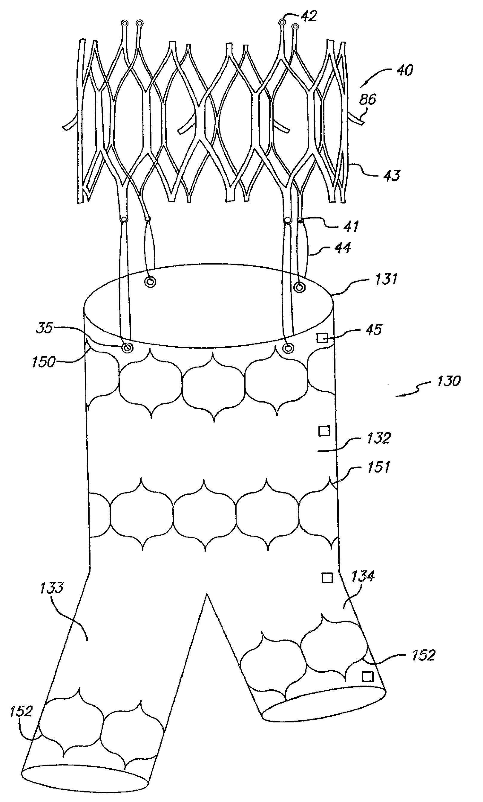
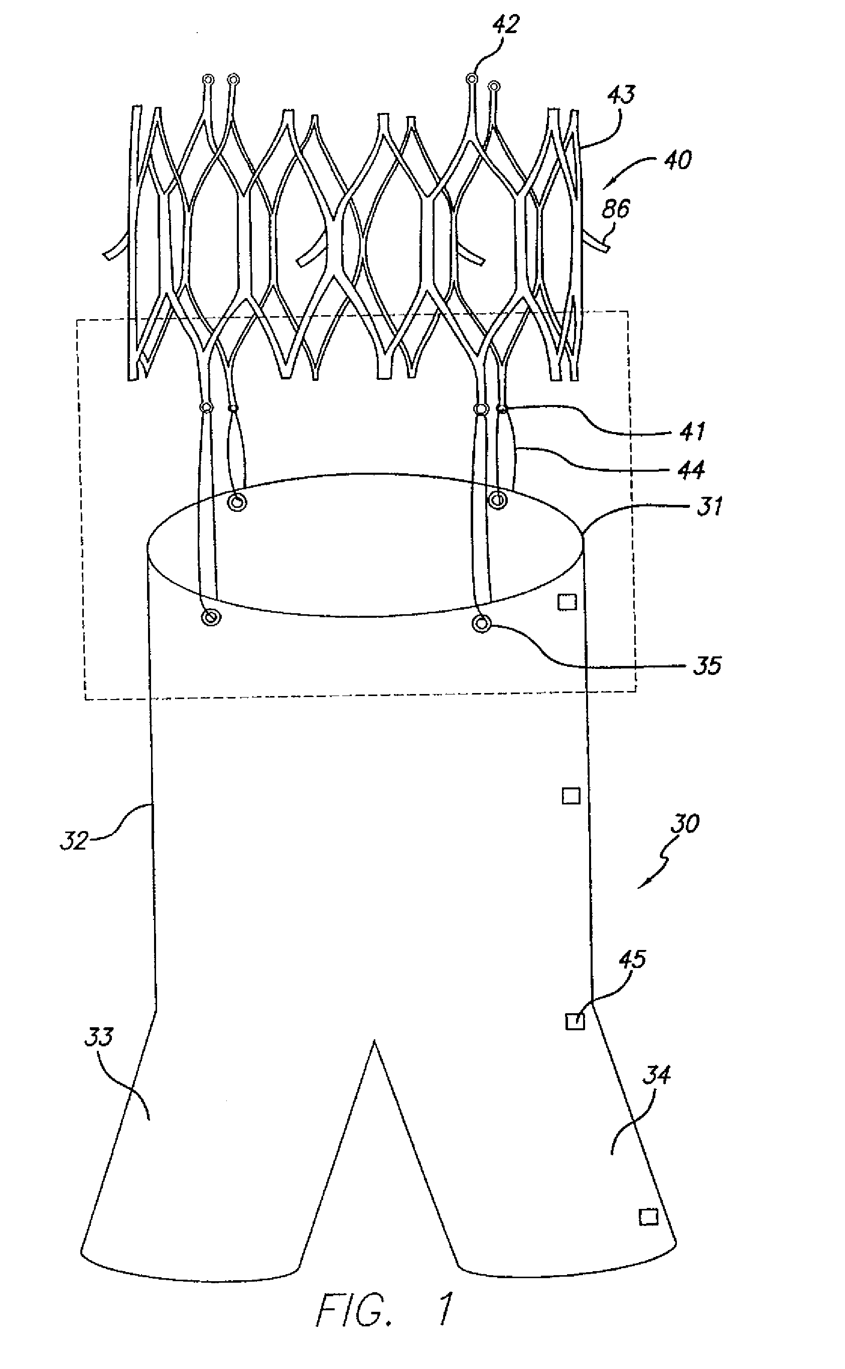
[0084]FIG. 1 shows the main body component 30 and attachment stent 40 of a bifurcated endovascular graft that is one aspect of the present invention. The main body component 30 consists of a superior end or neck 31, trunk 32 and two limb support portions 33, 34. The limb support portions 33, 34 facilitate insertion, deployment, and attachment of limb components of the modular endovascular graft. Radiopaque markers 45 placed along the contra-lateral side of the graft material identify the neck 31, mid-point, bifurcation, and distal end of the contra-lateral limb support portion 34, thereby facilitating placement within the patient's body.

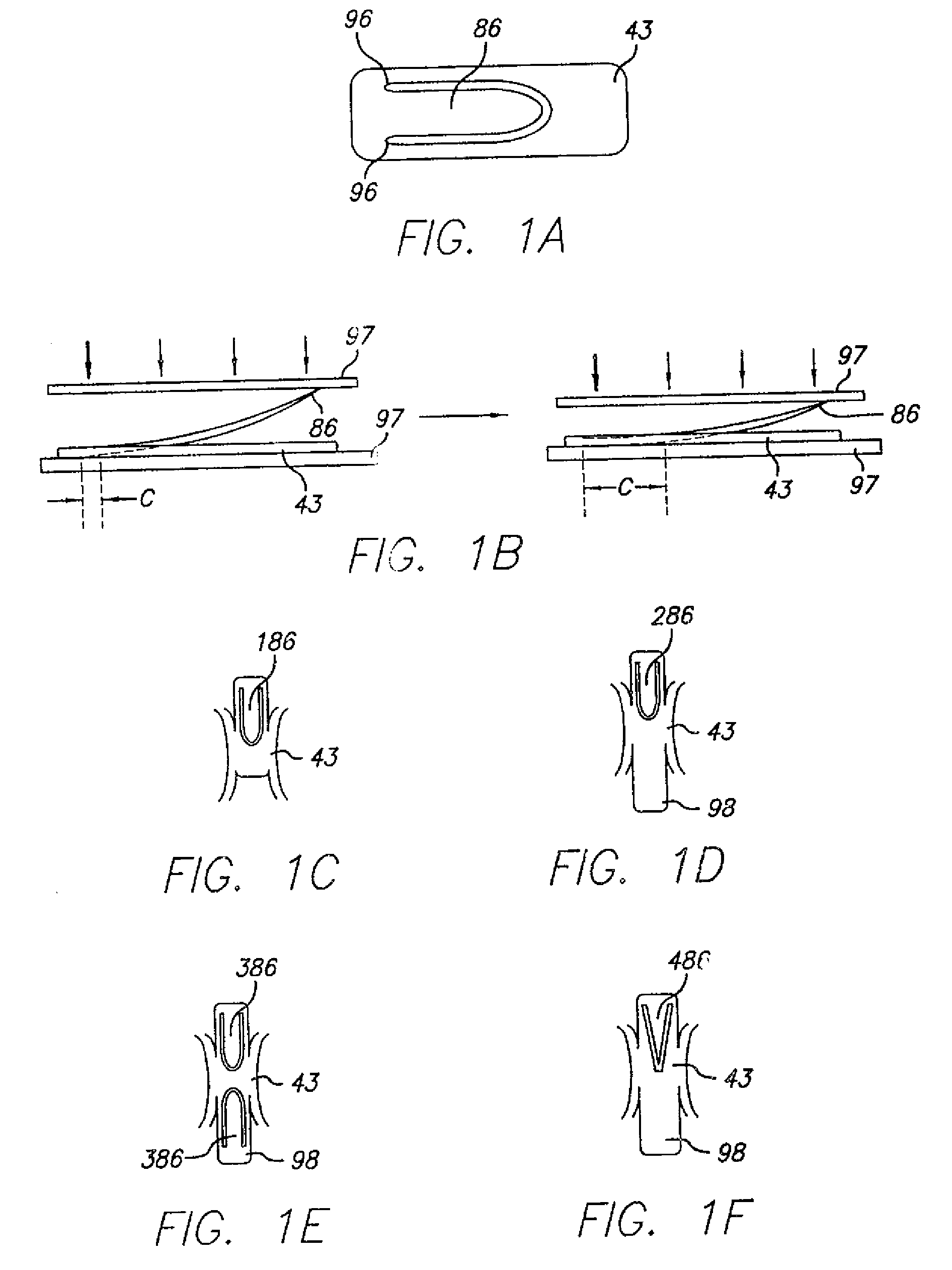
[0085]The anchoring or attachment stent 40 has connector eyelets 41 at its distal end, loading eyelets 42 at its proximal end, and attachment hooks or barbs 86 at its midpoint. The attachment stent 40 con...


PUM


Abstract

The present invention embodies an endovascular graft having various frame-to-main body component attachment mechanisms which provide a secured bond, reduced graft material wear, and reduced delivery profile.

Description

CROSS-REFERENCE TO RELATED APPLICATIONS[0001]This application is a Divisional of U.S. patent application Ser. No. 10 / 090,492, filed Mar. 2, 2002, which is a Non-Provisional of U.S. Provisional Patent Application No. 60 / 360,323, filed Feb. 26, 2002, both of which are herein incorporated by reference.BACKGROUND OF THE INVENTION[0002]This invention relates to an endovascular graft assembly for treating vasculature of a patient and more specifically to graft system and the attachment of structures thereof.[0003]It is well established that various fluid conducting body or corporeal lumens, such as veins and arteries, may deteriorate or suffer trauma so that repair is necessary. For example, various types of aneurysms or other deteriorative diseases may affect the ability of the lumen to conduct fluids and, in turn, may be life threatening. In some cases, the damage to the lumen is repairable only with the use of prosthesis such as an artificial vessel or graft.[0004]For repair of vital l...

Claims


Application Information

Patent Timeline
Patent Type & Authority Applications(United States)
IPC IPC(8): A61F2/06
CPCA61F2/07A61F2/91A61F2/915A61F2002/067A61F2002/075A61F2230/0054A61F2002/91558A61F2/89A61F2220/0075A61F2220/0008A61F2220/0016A61F2002/91541
Inventor CHUTER, TIMOTHY A.M.FITZ, MATTHEW J.ECKERT, ROBIN W.HOLT, VIVIANNE M.TON, TINAIANCEA, OCTAVIANPEREZ, JUAN I.NEWHAUSER, RICHARDUEMURA, SHUJIPOLLOCK, DAVID T.HAYASHI, REIDCAFFELL, GEORGE
Owner LIFEPORT SCI
Why Eureka
Try Eureka