Method and apparatus for automated storage and retrieval of miniature shelf keeping units

a shelf keeping unit and automated storage technology, applied in the field of automated chemical, pharmaceutical or biotech compound testing systems, can solve the problems of difficult, expensive and laborious assembly, and difficulty in reliably sealing each shelf keeping uni

Inactive Publication Date: 2010-06-24
LIMR CHEM GENOMICS CENT INC LCGC
View PDF24 Cites 5 Cited by
  • Summary
  • Abstract
  • Description
  • Claims
  • Application Information

AI Technical Summary

Benefits of technology

[0011]Accordingly, it is a primary object of the present invention to overcome the above mentioned difficulties by providing an economical and effective automated pharmaceutical or biotech compound testing system using a very small minitube shelf keeping unit.
[0022]During the heat sealing process, the minitube well plates are supported at the very bottom of the plate while the platen on top pushes down, so a very uniform pressure is applied, thereby achieving, among other things, enhanced reliability in the sealing of individual tubes.
[0024]The die cutter shape or dimensions are dictated in part by that goal. Particularly, the die cutter has an angled edge, e.g., 20 degrees to the inside, whereby a knife-like beveled edge is presented. That beveled edge is very sharp, from a design tradeoff perspective, the balance is between having a shallower angle (rendering cleaner cut) or a larger angle (rendering longer wear, for longevity). At present, the priority is functionally making clean cuts, so the individual minitube seals are reliably left intact after the cutting step has taken place. A sharp cutting edge also helps maintain the flatness of that planar surface, over the whole plate, during the removal of all the tubes. The removal process is usually random in that tubes are removed at one point and then another and another. The typical completely random request process for the chemicals in these tubes might have three or four tubes remaining right in the middle after everything else is punched out around them, and a relatively flat well-oriented web must be maintained to hold those tubes. Another advantage of a very sharp cutting beveled edge is that, in use, the minitube well plate remains substantially planar as the tubes are cut out.
[0025]The minitube itself is tapered from top to bottom, having a gently decreasing diameter from top to bottom and being circular in cross-section. The die cutter has an interior defining a straight cylinder. The cutting edge is on the outside of the cylinder, and the outside is tapered for strength. The die cutter body also has a taper at the top that creates the beveled knife edge. There is a dual taper there; a two degree taper mirroring the minitube sidewall, so the adjacent minitubes allow for a two degree outward taper on the die. The minitube uses every bit of material that will fit within the clearances defined by adjacent placements of the die cutter. The die cutter taper gives enhanced tool strength and the tapered area around each minitube allows for that clearance and allows the die cutter to have that taper outward.

Problems solved by technology

In prior art systems, shelf keeping unit parts are separately molded to provide, for example, an array of 384 miniature shelf keeping units or test tubes; the tubes are inserted in a matrix of 384 square sockets, thus requiring a very costly assembly.
The shelf keeping units or tubes of the prior art must be sealed for storage and automated handling and reliably sealing each shelf keeping unit is expensive and difficult, since each shelf keeping unit is small.

Method used


Image

  • Method and apparatus for automated storage and retrieval of miniature shelf keeping units
  • Method and apparatus for automated storage and retrieval of miniature shelf keeping units
  • Method and apparatus for automated storage and retrieval of miniature shelf keeping units

Examples


Embodiment Construction

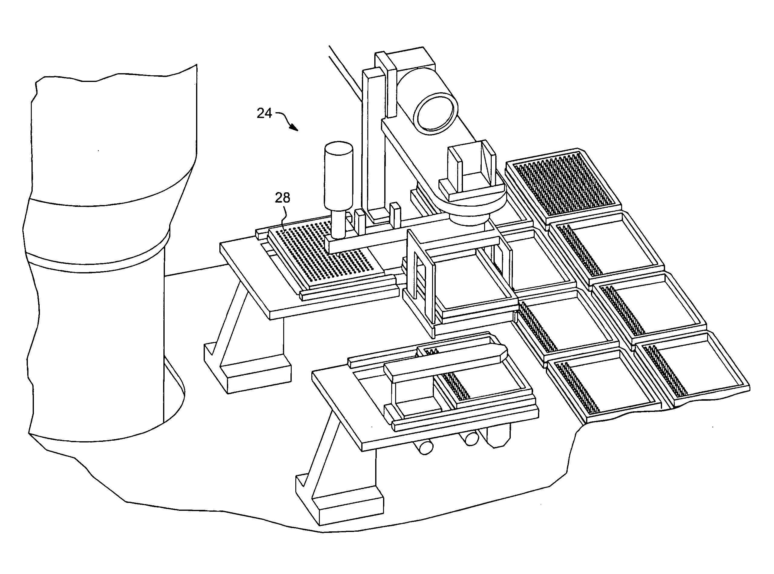
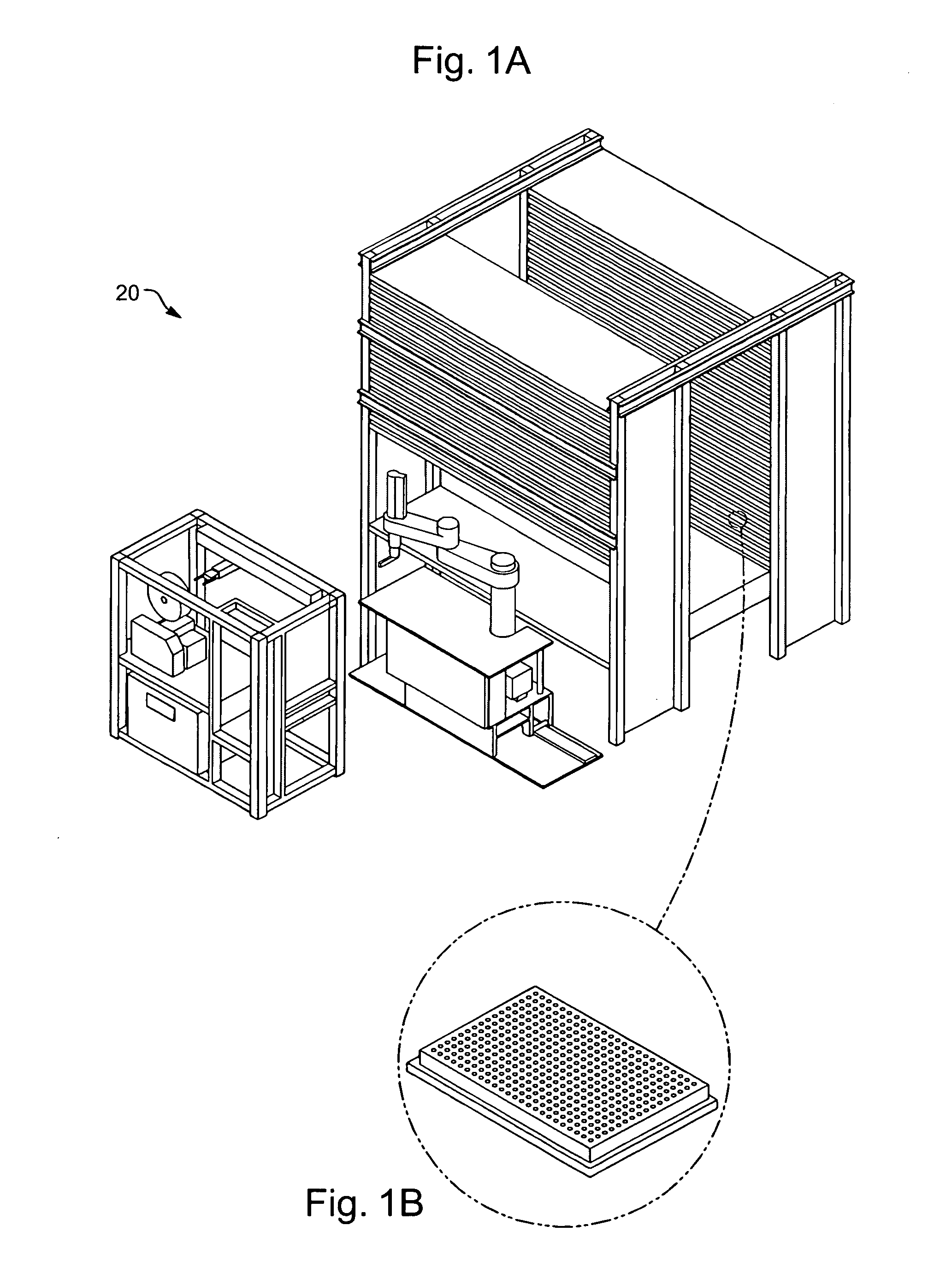
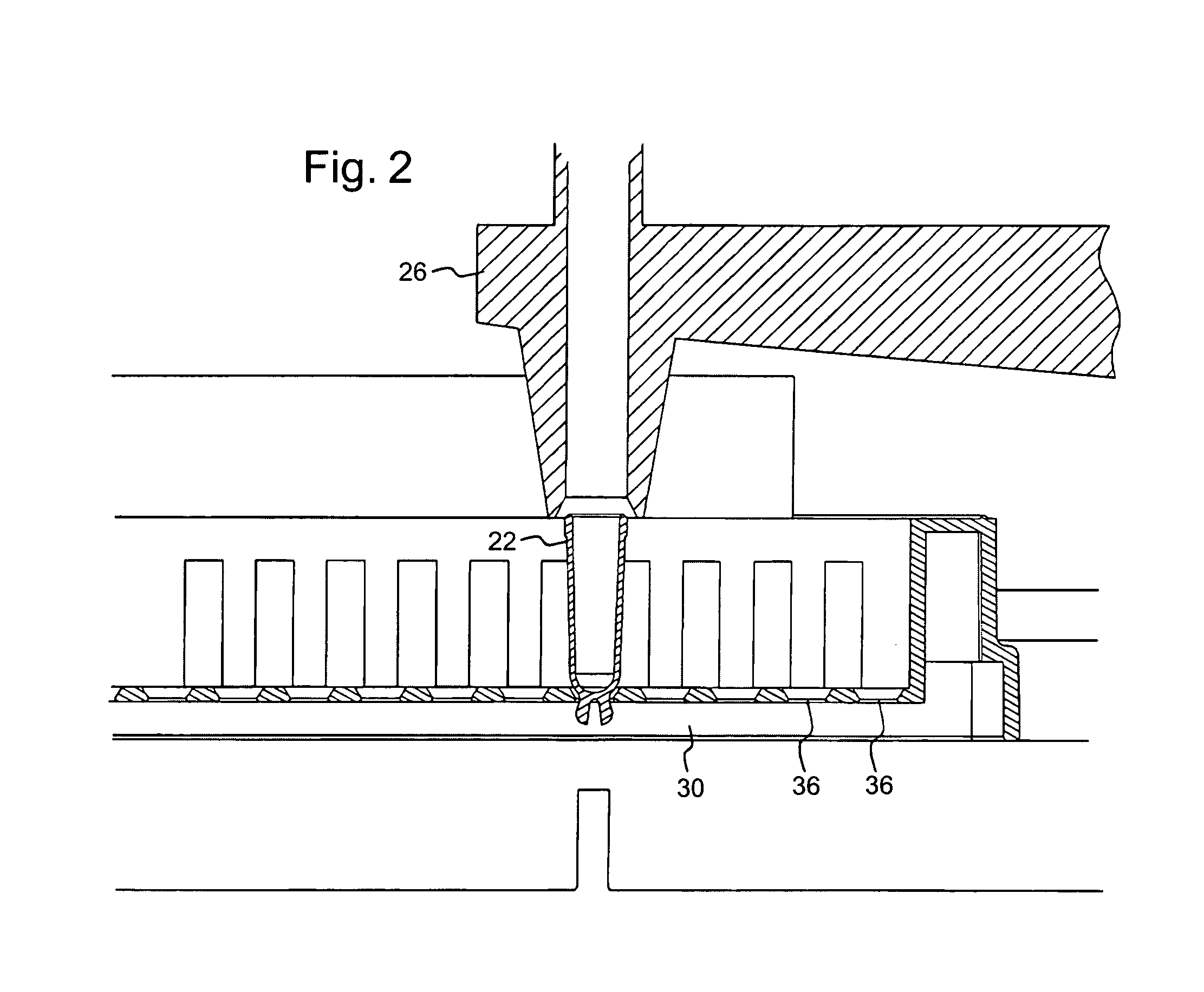
[0042]Referring now to FIGS. 1-15, in accordance with the present invention, an automated miniature shelf keeping unit storage and retrieval system 20 uses a very small molded plastic shelf keeping unit or test tube known as a “minitube”22. The minitubes 22 are stored in trays in (preferably) a standing refrigeration unit and are retrieved by a machine or robot 24 having a die cutting tubular end effector 26 adapted to selectively cut away and remove a minitube 22 from an integrally molded matrix 28 containing hundreds of minitubes (e.g., 384). The matrix is also called a minitube well plate 28 and preferably includes a sealing membrane or layer covering the upward facing openings of the minitubes. Upon cutting a selected minitube 22 away from the matrix, the end effector 26 is pushed over the selected minitube, thus forcing the minitube into the cylindrical interior lumen of the end effector 26, where it is retained by friction fit until such time as the minitube is to be releaseab...


PUM


Abstract

An automated pharmaceutical or biotech compound testing system uses a very small molded plastic shelf keeping unit or test tube known as a “minitube”. The minitubes are stored in trays in a standing refrigeration unit and are retrieved by a machine or robot having a die cutting tubular end effector adapted to selectively cut away and remove a minitube from an integrally molded matrix containing hundreds of minitubes (e.g., 384); the matrix is called a minitube well plate. Upon cutting a selected minitube away from the matrix, the end effector is pushed down over the selected minitube, thus forcing the minitube into the cylindrical interior lumen of the end effector, where it is retained by friction fit until such time as the minitube is to be releaseably locked into a plastic receiving tray. Minitubes are stored in the plastic tray which is adapted to receive and releaseably hold or lock the tubes in place. The minitubes themselves are molded plastic tubes having distally projecting spaced apart “rabbit ear” detent lock members which are biased outwardly. The plastic receiving tray has apertures sized to receive the minitubes and each aperture of the tray is terminated at bottom in a hole defined within chamfered shoulders adapted to slidably engage and exert transverse force against the minitube rabbit ears. The two rabbit ears and the hole together comprise a detent lock system, the minitube rabbit ears releaseably engage the shoulder surfaces on the bottom of the hole in each aperture of the tray. The robot end effector can withdraw and replace the tubes as needed to perform automated testing.

Description

PRIOR APPLICATION INFORMATION[0001]This application claims benefit from co-pending and commonly owned provisional patent application No. 60 / 340,284, which was filed Dec. 13, 2001, the entire disclosure of which is incorporated herein by reference.BACKGROUND OF THE INVENTION[0002]1. Field of the Invention[0003]The present invention relates to automated chemical, pharmaceutical or biotech compound testing systems using miniature shelf keeping units or test tubes. The shelf keeping units or test tubes are preferably stored in a standing refrigeration unit and are retrieved by a robot.[0004]2. Discussion of the Prior Art[0005]In prior art systems, shelf keeping unit parts are separately molded to provide, for example, an array of 384 miniature shelf keeping units or test tubes; the tubes are inserted in a matrix of 384 square sockets, thus requiring a very costly assembly.[0006]Industry standards promulgated (in draft form) by the Society for Biomolecular Screening (“SBS”) specify stand...

Claims


Application Information

Patent Timeline
Patent Type & Authority Applications(United States)
IPC IPC(8): B65G49/05G06F19/00
CPCB01L3/5082B01L3/50855B01L2300/0851B01L2200/025B01L2200/04B01L9/06
Inventor MASON, THOMAS K.
Owner LIMR CHEM GENOMICS CENT INC LCGC
Why Eureka
Try Eureka