Control device and control method for internal combustion engine

a control device and control method technology, applied in the direction of electric control, machines/engines, output power, etc., can solve the problems of likely deterioration of the response of the turbocharger, and achieve the effects of preventing the rich shift of air-fuel ratio, sufficient exhaust energy, and sufficient charging pressur

Inactive Publication Date: 2010-07-01
TOYOTA JIDOSHA KK
View PDF8 Cites 8 Cited by
  • Summary
  • Abstract
  • Description
  • Claims
  • Application Information

AI Technical Summary

Benefits of technology

[0029]In the fourth aspect of the invention, during the lean combustion, the second exhaust valve is brought to rest in the closed state, so that the entire amount of exhaust gas is supplied to the turbine. Furthermore the amount of overlap between the first exhaust valve and the intake valve is set less than th...

Problems solved by technology

Incidentally, during the lean combustion, the exhaust gas temperature is relatively low so that the re...

Method used


Image

  • Control device and control method for internal combustion engine
  • Control device and control method for internal combustion engine
  • Control device and control method for internal combustion engine

Examples


embodiment 1

Concrete Processes in Embodiment 1

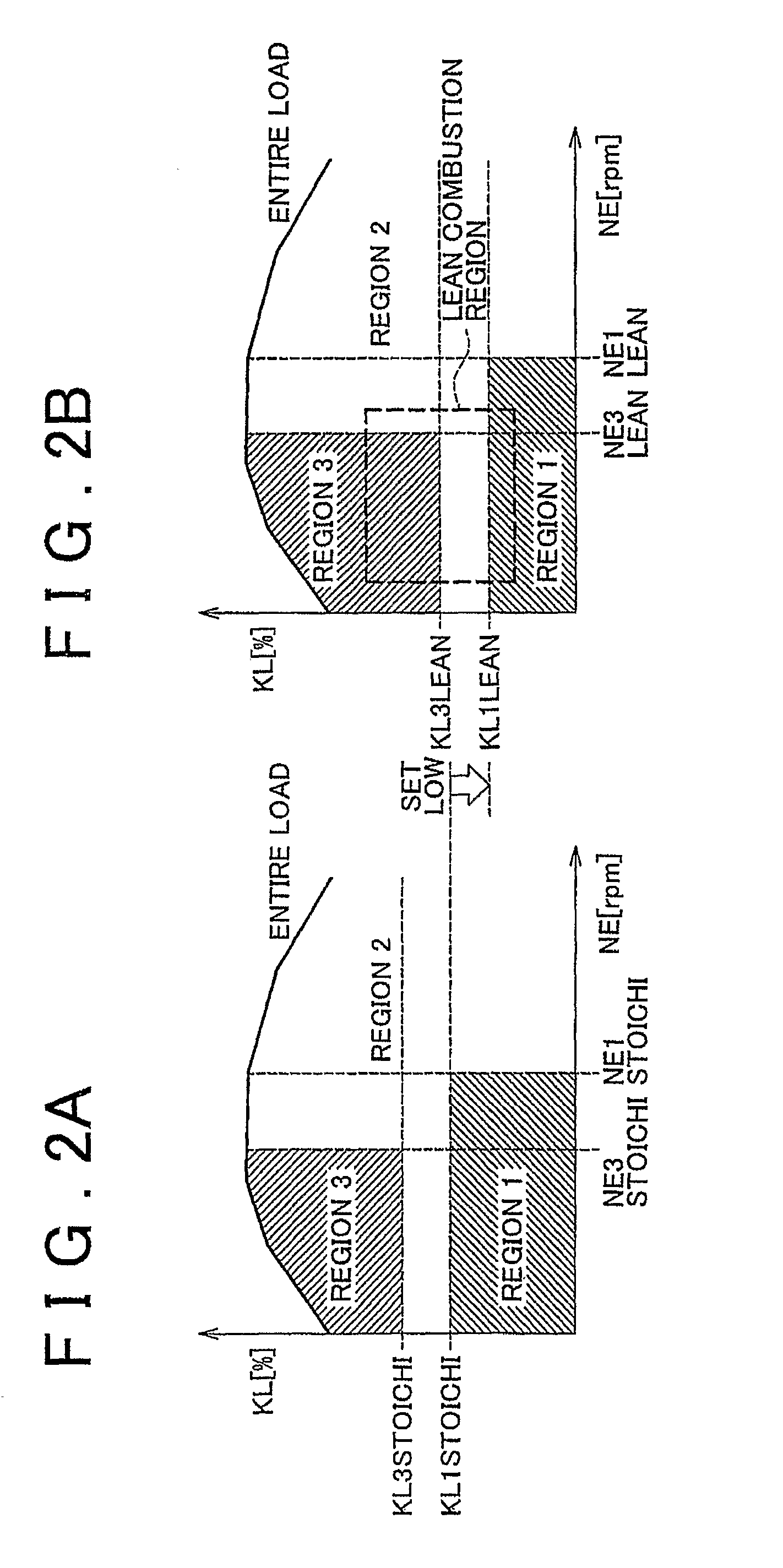
[0072]FIG. 4 is a flowchart showing a process that the ECU 60 executes in Embodiment 1. This process is started at a predetermined timing before the exhaust valves Ex1, Ex2 are driven. According to the process shown in FIG. 4, the engine rotation speed NE and the engine load KL are firstly read (step 100). Subsequently, the engine operation mode is referred to on the basis of the engine rotation speed NE and the engine load KL read in step 100 (step 102). It is to be noted herein that, in a process other than the present process, one of the stoichiometric combustion and the lean combustion is determined as the engine operation mode to be executed, on the basis of the engine rotation speed NE and the engine load KL. In the foregoing step 102, the thus-determined engine operation mode is referred to.

[0073]After that, it is determined whether or not the engine operation mode referred to in step 102 is the lean combustion or the rich spike control is be...

embodiment 2

Concrete Processes in Embodiment 2

[0093]FIG. 7 is a flowchart showing a process that the ECU 60 executes in Embodiment 2. This process is started at a predetermined timing before the exhaust valves Ex1, Ex2 are driven.

[0094]According to the process shown in FIG. 7, the process of steps 100 to 104 is firstly executed as in the process shown in FIG. 4. if in step 104 it is determined that the present engine operation mode is the stoichiometric combustion; NE1=NE1STOICHI and KL1=KL1STOICHI are calculated (step 110) as in the process shown in FIG. 4. After that, NE3=NE3STOICHI and KL3=KL3STOICHI are calculated (step 112).

[0095]On the other hand, if in step 104 it is determined that the present engine operation mode is the lean combustion or the rich spike control is being executed, the ECU 60 acquires the pre-catalyst bed temperature Tp and the NOx catalyst bed temperature Tnox (step 130), unlike the process shown in FIG. 4. After that, it is determined whether or not the pre-catalyst b...

embodiment 3

Concrete Processes of Embodiment 3

[0108]FIG. 11 is a flowchart showing a process that the ECU 60 executes in Embodiment 3. This process is started at a predetermined timing before the exhaust valves Ex1, Ex2 are driven.

[0109]According to the process shown in FIG. 11, the engine rotation speed NE and the engine load KL are read (step 100), and the engine operation mode is referred to (step 102), as in the process shown in FIG. 4. After that, it is determined whether or not the engine operation mode referred to in step 102 is the lean combustion (step 140). If in step 140 it is determined that the present engine operation mode is the stoichiometric combustion, the process is ended.

[0110]On the other hand, if in step 140 it is determined that the engine operation mode is the lean combustion, the pre-catalyst bed temperature Tp and the NOx catalyst bed temperature Tnox are acquired (step 130), as in the routine shown in FIG. 6. After that, it is determined whether or not the pre-catalys...


PUM


Abstract

In a region where the engine load is less than a first predetermined value, only a second exhaust valve that opens and closes a second exhaust passageway that bypasses a turbine of a supercharger is opened. In a region where the engine load is greater than or equal to the first predetermined value and less than a second predetermined value, both the second exhaust valve and a first exhaust valve that opens and closes a first exhaust passageway that leads to the turbine are opened. In a region where the engine load is greater than or equal to the second predetermined value, only the first exhaust valve is opened. A predetermined value for the time of lean combustion is set lower than a predetermined value for the time of stoichiometric combustion.

Description

BACKGROUND OF THE INVENTION[0001]1. Field of the Invention[0002]The invention relates to a control device and a control method for a turbocharger-equipped internal combustion engine, and more particularly to an exhaust valve control during lean combustion.[0003]2. Description of the Related Art[0004]There is a known device (independent exhaust type engine) that includes a first exhaust valve that opens and closes an exhaust passageway that leads to a turbine, and a second exhaust valve that opens and closes an exhaust passageway that does not lead to the turbine (see, e.g., Japanese Patent Application Publication No. 10-89106 (JP-A-10-89106)). According to this device, during a high-speed and high-load operation, the second exhaust valve that does not communicate with the turbine is opened at an earlier timing than the first exhaust valve that communicates with the turbine. This reduces the exhaust pumping loss, so that the output can be improved in a high-speed region.[0005]During ...

Claims


Application Information

Patent Timeline
IPC IPC(8): F02D45/00F01N3/10
CPCF01N3/2006F02B37/18F02D13/0257Y02T10/144Y02T10/26Y02T10/18F01N13/009Y02T10/12
Inventor HOKUTO, HIROYUKIKANEKO, NAOYA
Owner TOYOTA JIDOSHA KK
Why Eureka
Try Eureka