Gate driving circuit and display device having the gate driving circuit

a driving circuit and display device technology, applied in pulse generators, pulse techniques, instruments, etc., can solve the problems of increased resistive-capacitive delay, visible noise defects such as ripples, and achieve the effect of improving driving reliability

Inactive Publication Date: 2010-07-01
SAMSUNG DISPLAY CO LTD
View PDF7 Cites 49 Cited by
  • Summary
  • Abstract
  • Description
  • Claims
  • Application Information

AI Technical Summary

Benefits of technology

[0009]An aspect of the present invention provides a gate driving circuit capable of improving driving reliability by ensuring the timing margin of a gate signal.
[0022]According to exemplary embodiments of the present invention, a data charging rate may be improved by ensuring the timing margin of a gate signal, so that the driving reliability of the gate driving circuit may be improved.

Problems solved by technology

When the gate driving circuit integrated in the integrated circuit formed on the display substrate is driven in high temperature conditions, visible noise defects such as ripples may be generated during a “gate-OFF signal” period.
Moreover, as LCD panels become dimensionally larger, the resistive and capacitative loads of the lines in the LCD panels are increasing so that resistive-capacitive (RC) delay is increased.

Method used


Image

  • Gate driving circuit and display device having the gate driving circuit
  • Gate driving circuit and display device having the gate driving circuit
  • Gate driving circuit and display device having the gate driving circuit

Examples


Embodiment Construction

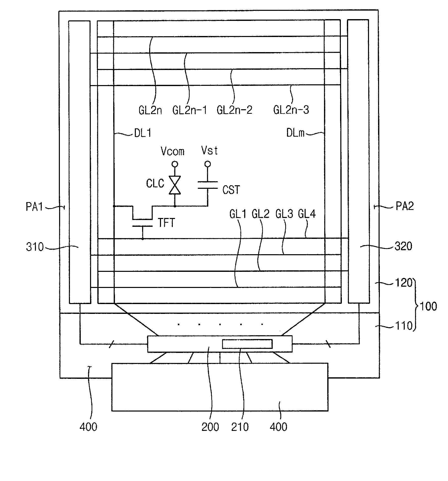
[0035]FIG. 1 is a plan view of a liquid crystal display (LCD) according to an exemplary embodiment of the present invention.

[0036]Referring to FIG. 1, a display device according to the present exemplary embodiment includes a display panel 100, a driving chip 200, a first gate driving circuit 310, a second gate driving circuit 320 and a printed circuit board (PCB) 400.

[0037]The display panel 100 may include a thin film transistor substrate (TFT) (display) substrate 110, an color filter substrate 120 opposite to the TFT substrate 110 and a liquid crystal layer (not shown) interposed between the TFT substrate 110 and the color filter substrate 120. The display panel 100 may include a display area DA which displays an image and a peripheral area PA which surrounds the display area DA.

[0038]A plurality of gate lines GL1 to GL2n (‘n’ is a natural number) and a plurality of data lines DL1 to DLm (‘m’ is a natural number) crossing the 2n gate lines GL1 to GL2n are formed on the TFT substrat...


PUM


Abstract

A gate driving circuit includes a first shift register and a second shift register for driving odd gate lines. The first shift register includes a first plurality of cascade-connected stages that sequentially output a plurality of first gate signals. A first stage of the first shift register receives a first vertical start signal. The second shift register includes a second plurality of cascade-connected stages to sequentially output a plurality of second gate signals. The first stage of the second shift register receives an output signal of the first stage of the first shift register as its vertical start signal. A data charging rate may be improved by ensuring the timing margin of each gate signal, so that the driving reliability of the gate driving circuit may be improved.

Description

PRIORITY STATEMENT[0001]This application claims priority, under 35 U.S.C. §119, of Korean Patent Application No. 2008-135415, filed on Dec. 29, 2008 in the Korean Intellectual Property Office (KIPO), the contents of which are herein incorporated by reference in their entirety.BACKGROUND OF THE INVENTION[0002]1. Field of the Invention[0003]The present invention relates to a gate driving circuit and a display device having the gate driving circuit. More particularly, the present invention relates to a gate driving circuit that drives a gate line and a display device having the gate driving circuit.[0004]2. Description of the Related Art[0005]Generally, a liquid crystal display (LCD) includes an LCD panel displaying an image by using the light transmissivity of liquid crystal, and a backlight assembly disposed behind the LCD panel to supply light to and through the LCD panel.[0006]The LCD further includes a gate driving circuit connected to a plurality of gate lines and a data driving ...

Claims


Application Information

Patent Timeline
Patent Type & Authority Applications(United States)
IPC IPC(8): G06F3/038H03K3/00
CPCG09G3/3677H03K19/00361G09G3/36G02F1/133G09G3/20H03K19/00
Inventor KIM, HAK-GYUPARK, YOUNG-JOOLIM, JI-SUK
Owner SAMSUNG DISPLAY CO LTD
Why Eureka
Try Eureka