

Communication device, integrated circuit, transmission rate control method, and transmission rate control program
- Summary
- Abstract
- Description
- Claims
- Application Information
AI Technical Summary
Benefits of technology
Problems solved by technology
Method used
Image

Examples
embodiment 1
Summary
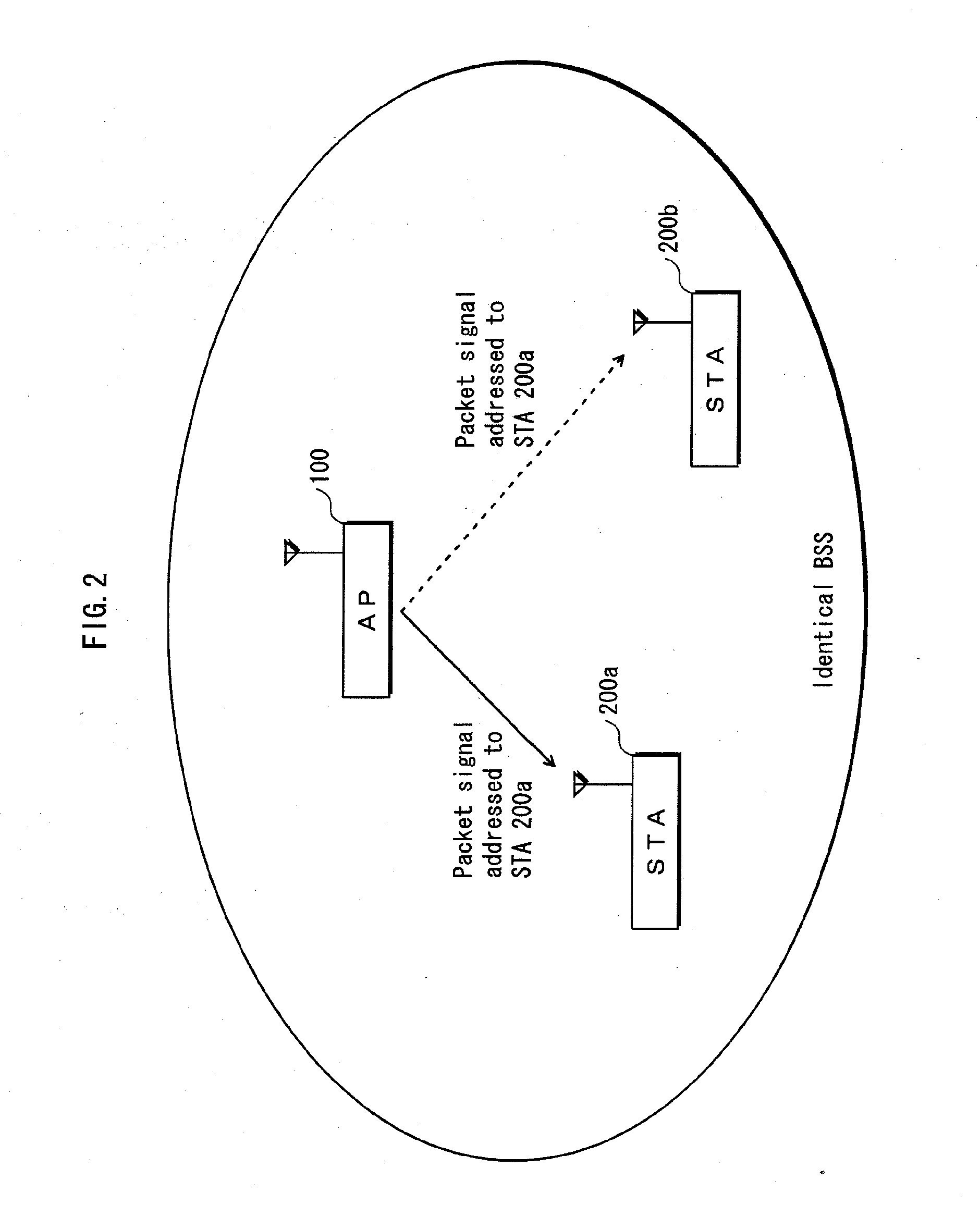
[0075]Conventionally, an STA measured reception intensity only upon receiving a signal addressed to the own station. In contrast, in the present invention, an STA also measures reception intensity on receiving a signal addressed to another station and notifies it to an AP. Accordingly, the present invention raises determination frequency of PHY rates, and makes it possible to determine PHY rates according to the channel environment changes as far as possible.
[0076]
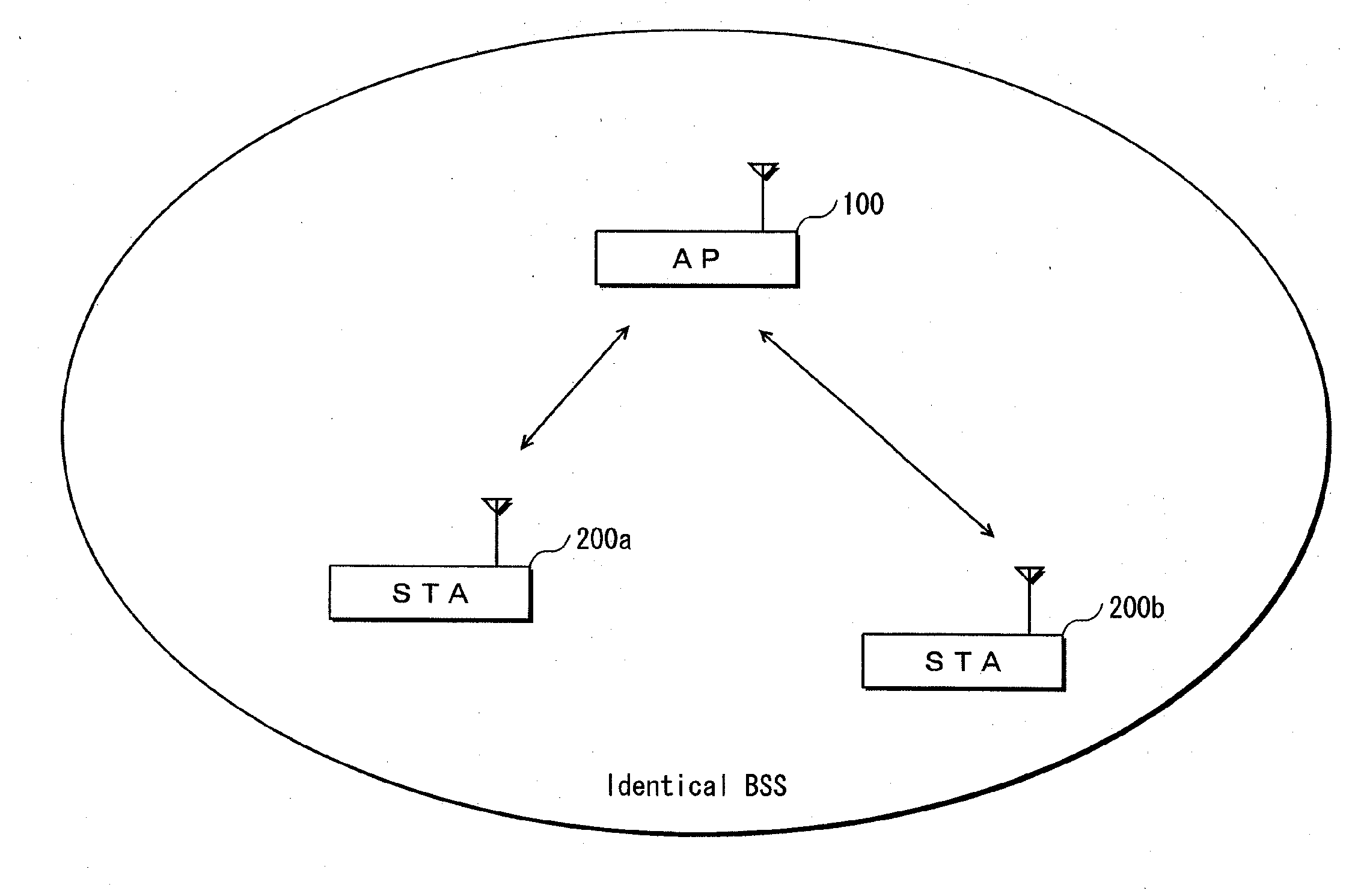
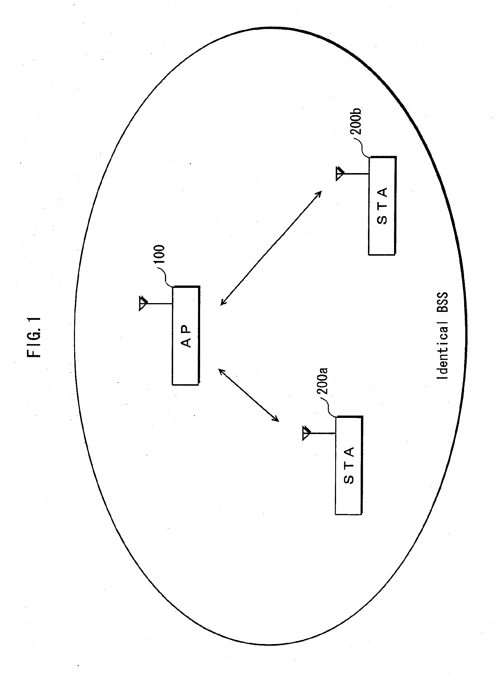
[0077]FIG. 1 is a network configuration diagram showing a system configuration in which communication devices are included. As shown in FIG. 1, an AP (Access Point) 100, an STA (Station) 200a, and an STA 200b are included within an identical BSS (Basic Service Set). One of the above-mentioned communication devices corresponds to the AP 100, and the first and second communication terminals correspond to the STA 200a, 200b. The AP 100 comprises a standard feature of an access point, and the STA 200a, 200b comprise a s...
embodiment 2
[0152]We have mentioned that, in Embodiment 1, an STA receives a signal addressed to the other station, measures an RSSI, and notifies the measured RSSI to the AP, enabling its PHY rate determination and update frequency to be quicker than before. Meanwhile, propagation characteristics shown by the propagation characteristics information are used for the PHY rate determination. Since the propagation characteristics vary in response to channel environments, it is preferable to correct them.
[0153]So now, in Embodiment 2, description will be made on correction of propagation characteristics.
[0154]
[0155]FIG. 12 shows a network configuration in Embodiment 2. An AP 300, STA 400a, and an STA 400b are included in an identical BSS.
[0156]FIG. 13 is a functional block diagram showing a functional structure of the AP 300.
[0157]As shown in FIG. 13, the AP 300 includes a RF processing unit 101, a PHY layer processing unit 102, a MAC layer processing unit 103, an upper layer processing unit 104, a...
embodiment 3
[0190]As we have mentioned, in Embodiment 1, a PHY rate is determined based on propagation characteristics and a threshold PER value. Yet, it is also possible to use another method for determining the PHY rate. In Embodiment 3, an effective transmission velocity (which is also referred to as throughput) is estimated, so as to determine the PHY rate based on it.
[0191]
[0192]FIG. 19 shows a network configuration in Embodiment 3. An AP 500a, an STA 600a, and an STA 600b are included within an identical BSS.
[0193]FIG. 20 is a functional block diagram showing the functional structure of the AP 500.
[0194]As shown in FIG. 20, the AP 500 includes an RF processing unit 101, a PHY layer processing unit 102, a MAC layer processing unit 103, an upper layer processing unit 104, a propagation characteristics storing unit 109, a state notice analyzing unit 335, a correction processing unit 336, a throughput estimating unit 501, and a PHY rate determining unit 502. Since the AP 500 has a substantial...
PUM
 Abstract
Description
Claims
Application Information