
Car power source apparatus

Active Publication Date: 2010-07-01
SANYO ELECTRIC CO LTD
View PDF5 Cites 66 Cited by
  • Summary
  • Abstract
  • Description
  • Claims
  • Application Information

AI Technical Summary

Benefits of technology

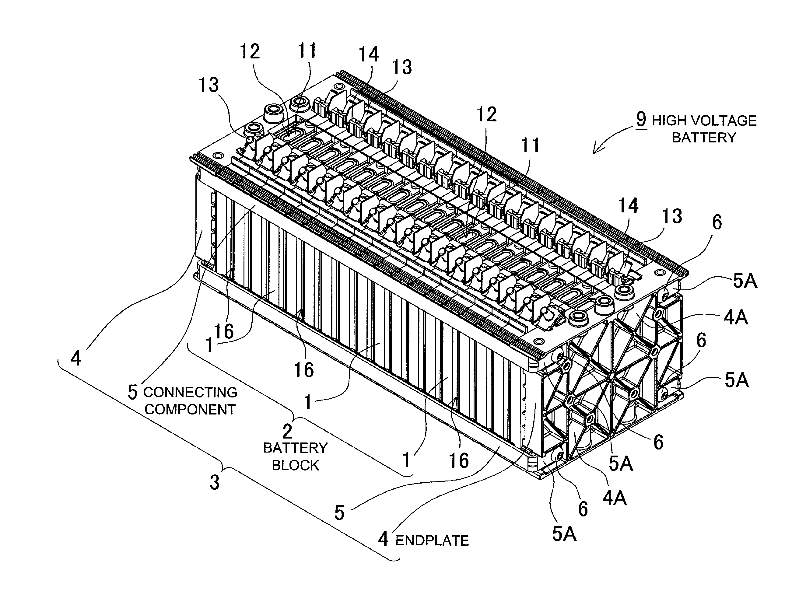
[0008]The car power source apparatus described above realizes the extremely important characteristic for a car power source apparatus that battery cell safety is improved by housing a current interrupt device in each battery cell to cut-off current when internal battery pressure rises abnormally, and current interrupt device cut-off due to vehicle vibration is effectively prevented. This is because the case of each battery cell housing a current interrupt device has a pair of opposing planar surfaces of rectangular shape; and an electrode unit that is a stack of positive and negative electrode plates with intervening separators, and a current interrupt device are disposed between that pair of opposing planar surfaces. Further, a plurality of battery cells are stacked with opposing planar surfaces opposite each other to form a battery block, a pair of endplates is disposed at both ends of the battery block, the two endplates are connected by connecting components, and the stack of battery cells held by the endplates is retained with pressure applied in a direction perpendicular to the opposing planar surfaces. In this power source apparatus, an electrode unit and current interrupt device are disposed between the opposing planar surfaces of each battery cell, a plurality of these battery cells is stacked to form a battery block, and pressure is applied to both ends of the battery block by the endplates to compress the opposing planar surfaces of the battery cell cases. Consequently, the electrode unit and current interrupt device of each battery cell are maintained in a compressed state by the opposing planar surfaces, and the electrode unit and current interrupt device do not move due to vibration. Therefore, disconnection of the connection region and current cut-off are prevented by the electrode unit and current interrupt device moving together.
[0017]In the car power source apparatus of the present invention, the current interrupt device 30, 40 can be connected between an electrode terminal 32 and an electrode tab 31 connected to the electrode unit 10. This car power source apparatus can prevent any movement due to electrode tab vibration by reliably retaining the electrode unit and current interrupt device with pressure applied to opposing planar surfaces of the case. Therefore, separation of the connection region of the current interrupt device, which is connected to an electrode tab, can be effectively prevented. The above and further objects of the present invention as well as the features thereof will become more apparent from the following detailed description to be made in conjunction with the accompanying drawings.

Problems solved by technology

However, this battery has the drawback that the current interrupt device can be damaged by vibration to cut-off current and make the battery unusable.
This is because vehicle vibration can cause the electrodes to move inside the battery case putting a load on the connection region of the current interrupt device.
The connection region of the current interrupt device is designed with a connection strength that results in separation and current cut-off when internal battery pressure rises abnormally.
If the connection region is too strong, it will be unable to separate and cut-off current when internal pressure rises abnormally.
Consequently, there are constraints on the strength of the connection region, and it has the drawback that it separates easily with vibration.
In particular, for batteries installed on-board a vehicle, vehicle vibration during driving cannot be eliminated, and the current interrupt device can cut-off current due to the vehicle vibration.
If the current interrupt device of a battery in a car power source apparatus cuts-off current during driving, the motor will stop suddenly and it will be impossible to maintain smooth driving.
Even worse, this battery has the drawback that in a pure electric automobile, the vehicle becomes completely unable to drive.

Method used


Image

  • Car power source apparatus
  • Car power source apparatus
  • Car power source apparatus

Examples


Embodiment Construction

)

[0029]The car power source apparatus of the present invention is primarily suitable as a power source apparatus for use on-board an electrically driven vehicle such as a hybrid car or electric automobile to supply power to a driving motor to drive the vehicle.

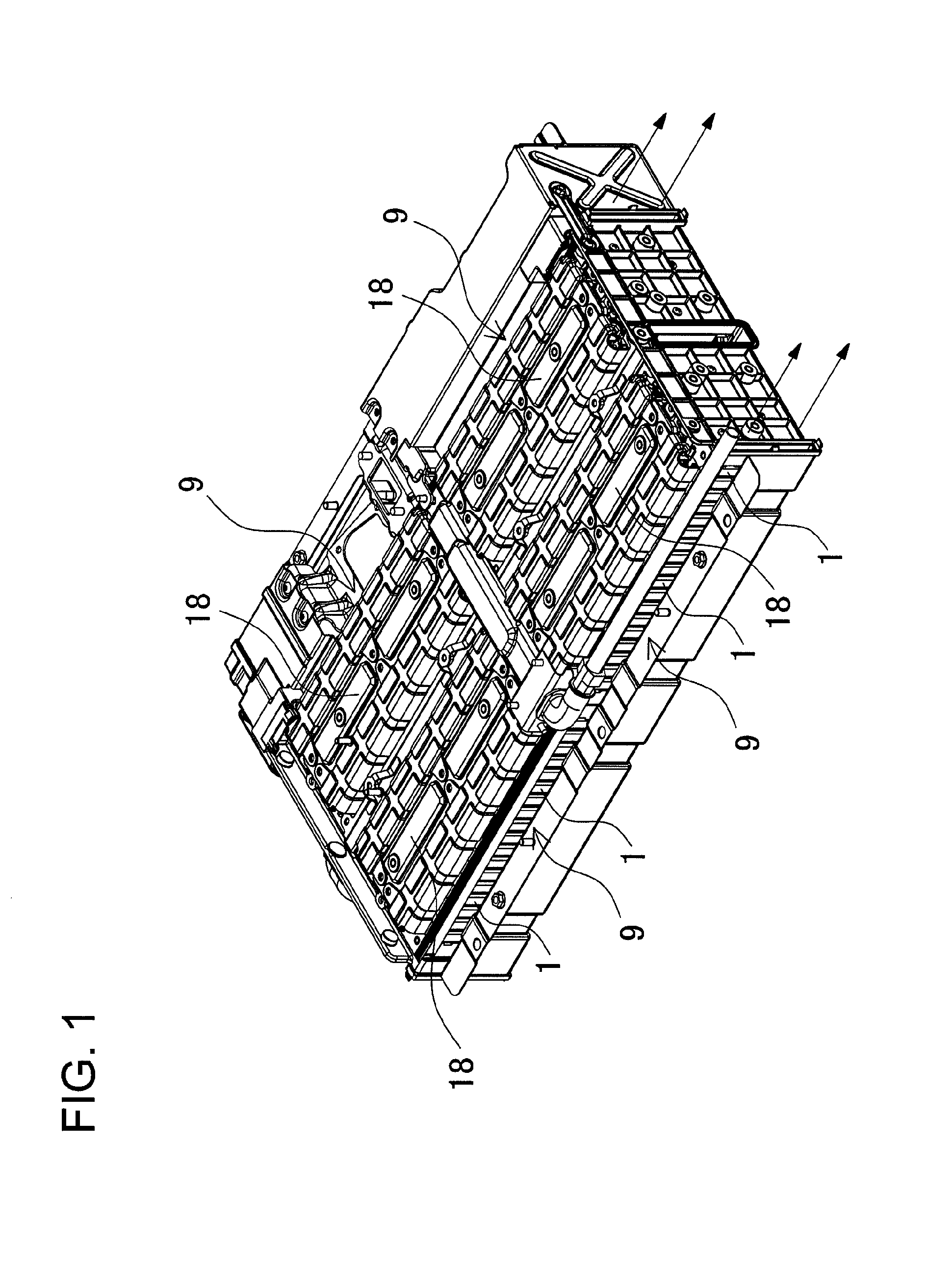
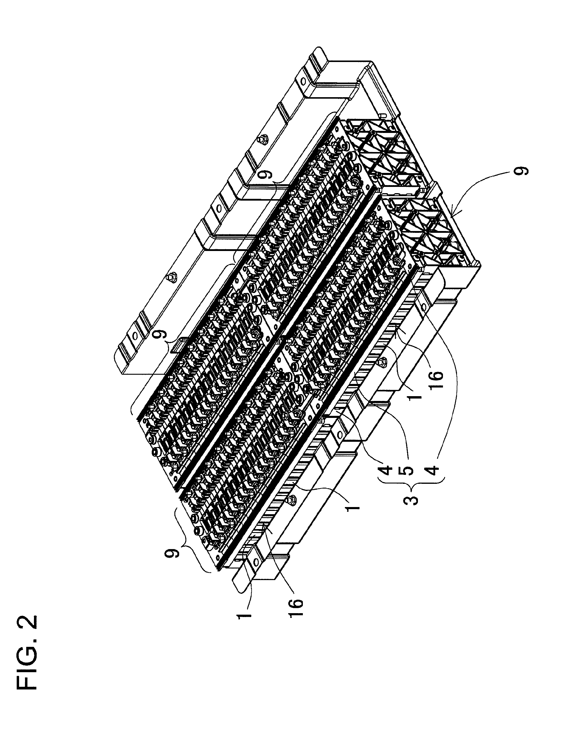
[0030]The car power source apparatus of FIGS. 1-5 is provided with a high voltage battery 9 that has a plurality of rechargeable battery cells 1 connected in series to increase output voltage. The power source apparatus of FIGS. 1 and 2 is provided with four high voltage batteries 9. A high voltage battery 9 preferably has all battery cells 1 connected in series to increase output voltage. However, a high voltage battery can also have a plurality of battery cells connected in parallel and those parallel connected battery cells can in turn be connected in series.

[0031]The rechargeable battery cells 1 are lithium ion batteries. However, any batteries that can be recharged, such as nickel hydride batteries or nickel cadmium batte...


PUM


Abstract

A case 20 of each battery cell 1 houses a current interrupt device 30 that cuts-off current when internal pressure exceeds a set pressure. The case has a rectangular outline with a pair of opposing planar surfaces 20A. An electrode unit 10, which is a stack of positive and negative electrode plates 10A with intervening separators 10C, and the current interrupt device 30 are disposed between the pair of opposing planar surfaces. A plurality of battery cells is stacked with opposing planar surfaces 20A opposite each other to form a battery block 2. The power source apparatus has a pair of endplates 4 disposed at the ends of the battery block 2, the pair of endplates 4 is connected by connecting components 5, and the pair of endplates 4 holds the battery cells 1 in the stacked configuration applying pressure in a direction perpendicular to the opposing planar surfaces 20A.

Description

BACKGROUND OF THE INVENTION[0001]1. Field of the Invention[0002]The present invention relates to a car power source apparatus that supplies power to a motor that drives the vehicle.[0003]2. Description of the Related Art[0004]To increase power supplied to the motor that drives a vehicle, the car power source apparatus increases output voltage of a battery block by connecting many rechargeable batteries in series to form that battery block. This car power source apparatus is discharged to supply power to the motor when the vehicle is driven, and is charged by a generator during regenerative braking of the vehicle. Battery discharge current determines the driving torque of the motor, and battery charging current determines the braking performance of the regenerative braking system. Therefore, to increase the driving torque of the motor that accelerates the vehicle, it is necessary to increase battery discharge current. To improve regenerative braking, charging at high currents is requ...

Claims


Application Information

Patent Timeline
IPC IPC(8): H01M2/24H01M50/529B60L50/64H01M50/528
CPCH01M2/1077H01M2/1083H01M2/1094H01M2/1229H01M2/34H01M2/345Y02E60/10H01M50/24H01M50/325H01M50/249H01M50/209B60L50/64H01M50/224H01M50/574H01M50/271Y02T10/70H01M10/48H01M50/204H01M50/242H01M50/572H01M50/578H01M2220/20
Inventor OKADA, WATARU
Owner SANYO ELECTRIC CO LTD
Learn More