
MR-Tracking Based on Magnetic Signature Selective Excitation

Active Publication Date: 2010-07-01
VAL CHUM PARTNERSHIP +1
View PDF7 Cites 23 Cited by
  • Summary
  • Abstract
  • Description
  • Claims
  • Application Information

AI Technical Summary

Benefits of technology

[0012]Another object of the present invention is to provide a tracking method and device whose resolution, precision and required acquisition time overcome the disadvantages of previous passive MR-tracking methods where the necessary acquisition and processing time and the poor resolution prevent their use for clinical applications.
[0013]A further object of the present invention is to provide a tracking method and device which rely on a new sequence that is easy to use with clinical MRI system and thus may be customized depending on the application requirements.

Problems solved by technology

These passive methods are typically simpler but slower compared to other methods.
The complexity of the inserted device increases substantially with an active method with the addition of an antenna to measure the induced NMR (Nuclear Magnetic Resonance) signals from the surrounding protons to determine the position through three axial projections.
Unlike passive methods, substantial increases in temperature, problematic for human interventions have been recorded in both active and semi-active tracking methods mainly due to the induced current along the length of the conducting wires by the applied RF (Radio Frequency) waves.
As such, being unable to track such a device within specific real-time constraints would prevent the feasibility of such an interventional technique.
These markers produce local field distortions appearing as areas of signal loss in MR imaging in a region surrounding the markers.
Furthermore, this positioning by signal loss, referred to as negative contrast, is limited to regions of high signal intensity where the signal loss can be detected without ambiguity.
Unfortunately, these methods are still image-based methods.
Although trade-offs may be achieved between spatial and temporal resolutions, these methods are far too slow in achieving an acceptable spatial resolution to be integrated within the real-time constraints of MRP-based applications.
However, this method does not deal with image artifacts and only applies within a given 2D image slice.

Method used


Image

  • MR-Tracking Based on Magnetic Signature Selective Excitation
  • MR-Tracking Based on Magnetic Signature Selective Excitation
  • MR-Tracking Based on Magnetic Signature Selective Excitation

Examples


example of application

[0082]It is possible to mount a magnetic-susceptible object on a tethered probe, such as on the tip of a catheter, so as to perform an exploratory, a diagnosis or curative intervention, for example in the vascular system of a subject. In this manner, the tethered probe can be precisely located during the intervention by tracking the magnetic-susceptible object provided on the tip thereof.

[0083]An example of a magnetic-susceptible object is a coil made of 30 gauge wire enrolled about 12 times at the ens of a 1.2 mm coaxial cable can be used to induce inhomogeneities in the magnetic field.

[0084]Before performing such an intervention, the vascular map of the subject on which the intervention is to be performed must be known. Accordingly, at the beginning of the intervention session, one can use the MRI system to acquire sufficient data to accurately represent the vascular map of the subject in 3D coordinate system. With this map, an intervention can be planned, i.e. the path that the t...


PUM


Abstract

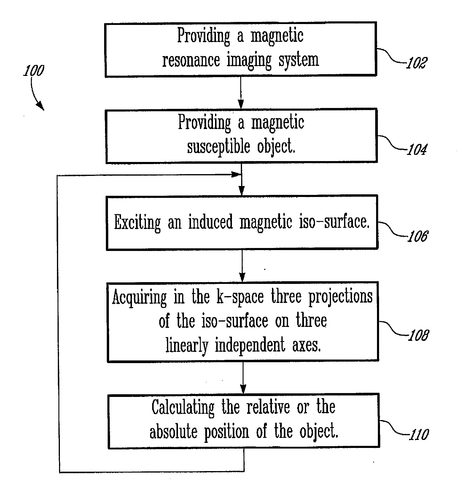
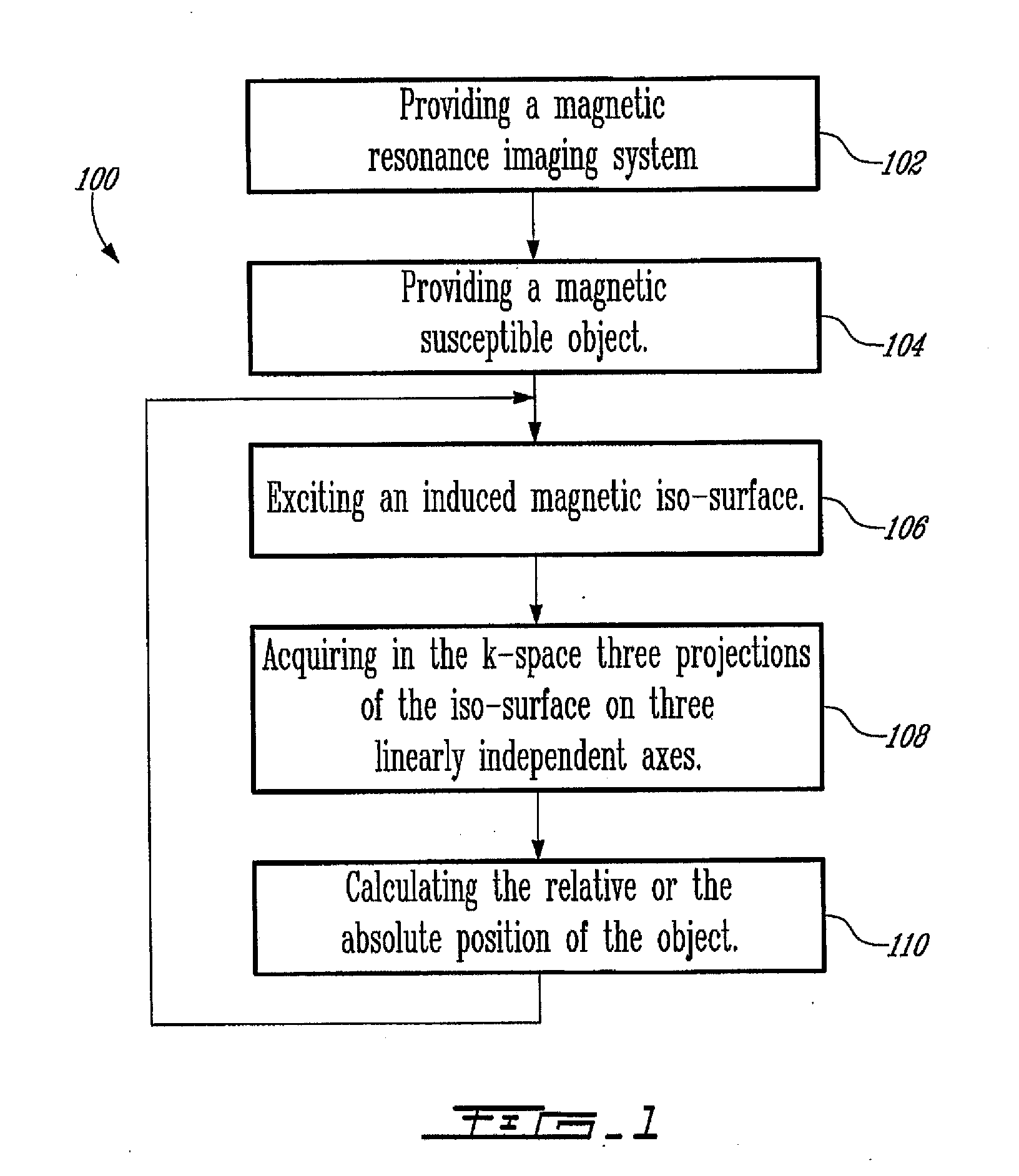
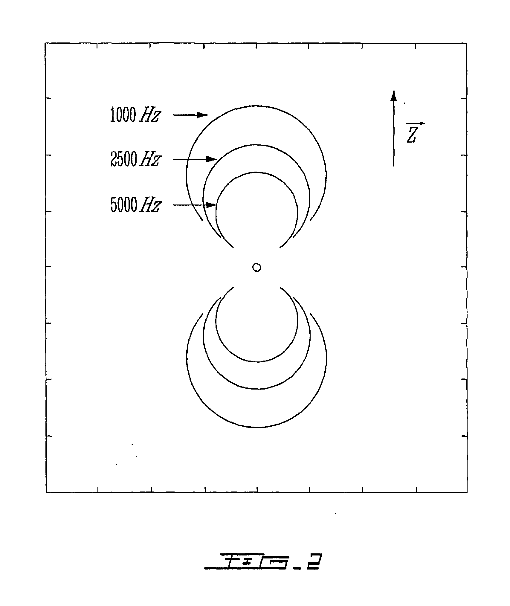
The present invention relates to a MR tracking method and device. More specifically, the present invention relates to a magnetic resonance tracking method and device, using a magnetic-susceptible object. A magnetic iso-surface induced by the object is selectively excited with a corresponding frequency offset; the magnetic iso-surface is then projected on three axes of a k-space, from which projections the spatial position of the object is calculated.

Description

FIELD OF THE INVENTION[0001]The present invention generally relates to a tracking method and device for tracking tethered and untethered objects inside the human body.BACKGROUND OF THE INVENTION[0002]Consistent and reliable tracking of an inserted device is one of the critical requirements for the success of MR-guided (Magnetic Resonance) endovascular interventions and as such, several methods have been reported. These tracking methods may be categorized either as passive, semi-active, or active.[0003]Passive tracking methods exploit the susceptibility difference between the tissue and the inserted device. These passive methods are typically simpler but slower compared to other methods.[0004]Semi-active methods are similar to the passive methods except that the susceptibility difference necessary to cause a signal loss is controlled through external means. This is typically done through the induction of a magnetic field that modifies the MR-signal by activating a coil integrated as ...

Claims


Application Information

Patent Timeline
IPC IPC(8): A61B5/055
CPCA61B5/055G01R33/286G01R33/287A61B90/36A61B2090/374A61B34/20
Inventor MARTEL, SYLVAINMATHIEU, JEAN-BAPTISTEFELFOUL, OUAJDIBEAUDOIN, GILLES
Owner VAL CHUM PARTNERSHIP
Learn More