Oesophageal treatment apparatus

a technology for oesophageal and oesophageal tubes, which is applied in the field of oesophageal treatment apparatuses and methods of treating tissue, can solve the problems of inflamed and irritated oesophageal tubes, pain and heartburn symptoms, and the development of cancer in the lower part of the oesophageal tube, so as to prevent erroneous signals from reaching the patient, the effect of fas

Inactive Publication Date: 2010-07-01
MEDICAL DEVICE INNOVATIONS
View PDF27 Cites 60 Cited by
  • Summary
  • Abstract
  • Description
  • Claims
  • Application Information

AI Technical Summary

Benefits of technology

[0093]The signal is preferably modulated to improve the transfer of energy to the tissue to be treated. Preferably, the modulator is arranged to produce a pulsed signal to be provided to the probe. A pulsed signal may permit a higher power level to be applied over a shorter period of time to achieve a predetermined energy dose. Pulsing in this way is effective where the desired form of energy transport from the probe to the tissue to be treated is radiation. Disadvantageous effects associated with conduction, such as conductive heating of the probe and its feed cable, can therefore be mitigated.
[0094]The modulator may be a pin diode switch. Thus, the apparatus may be arranged to deliver controlled programmable doses of energy using a stable source oscillator (e.g. having a frequency stability of less that 10 kHz at 14.5 GHz), a PIN diode absorptive switch modulator with breakthrough protection (to prevent switch frequency components from escaping to the amplifier or microwave source), a PIN diode absorptive attenuator (power level setter), a solid state amplifier line-up (e.g. pre-amplifier and main power amplifier) and directional couplers to measure forward and reflected power levels. The controller may include a first microprocessor for operating the above microwave components, and (optionally) a second microprocessor to monitor fault conditions, i.e. malfunction of first microprocessor or power supply line faults. Energy flow through the system into the patient may be controllable via a footswitch. The footswitch may be of the simple on / off (i.e. normally open (NO) or normally closed (NC)) type. Preferably, a DC isolation path circuit is included to ensure that no DC path exists between the generator and the user / operator.
[0095]The above apparatus may enable fine precision control of the delivered power level in either a pulsed or a continuous mode of operation. In pulse mode operation, duty cycles are selected to provide optimal tissue effect. Pulse mode enables high pulse power levels to be maintained for short periods of time, for example, a treatment structure that may be operated at 50 W in continuous mode operation, may be operated at 200 W for short durations of time, for example 50 ms with a duty cycle of 1:10. This operation offers the significant advantages where the energy transport mechanism is radiation. This form of operation also offers the advantage of extremely fast treatment time and eliminates problems associated with conductive heating of treatment antenna probes, flexible semi-rigid cable feed assemblies and the flexible co-axial cable assembly. It is also possible for the controller to send bursts of pulses with pre-selected pulse amplitudes and widths (e.g. 10 pulses of width 10 ms, 50% duty cycle and amplitude 10 W followed by 20 pulses of width 2 ms, 20% duty cycle and amplitude 40 W). Such pulse sequences may be selected to treat and are particularly suitable for treating a certain condition. It is also possible to use the microprocessor to generate a variety of pulse shapes, e.g. square, ramp, triangular, sine, etc.
[0096]Preferably, the controller is arranged to monitor the source of microwave radiation to prevent erroneous signals from reaching the probe. For example, the controller may check that the frequency of delivered radiation does not deviate outside a predetermined bandwidth associated with the fixed frequency. It may be preferable to use a second microprocessor to monitor this function.
[0097]Preferably, there is an isolation barrier between the probe and the rest of the apparatus, the isolation barrier being arranged to prevent direct current from flowing through the probe and into the patient.
[0098]In a preferred embodiment, the apparatus preferably comprises a stable frequency source, a pulse modulator with DC and low frequency breakthrough suppression, a wide range digitally controlled attenuator, a pre-amplifier and power amplifier with reflected power level protection and a DC system to user isolation barrier, forward and reflected power monitors and detectors, a flexible co-axial cable assembly, a flexible semi-rigid cable assembly (suitable for insertion into the oesophagus) and a probe comprising: a patch antenna array fabricated onto flexible substrate material, a means of opening and closing said patch antenna array within the oesophagus, a microprocessor for controlling the microwave radiation producing components, and an on / off footswitch circuit for operating the apparatus with a DC isolation barrier between the system and the external footswitch cable.

Problems solved by technology

Over a variable period of time it can occasionally lead to cancer developing in the lower part of the oesophagus.
The acid may inflame and irritate the oesophagus, and in some people will cause symptoms of pain and heartburn.
The liquid can inflame and damage the lining of the oesophagus.
Pepsin and bile also may injure the oesophagus.
Once it begins, it usually is life-long.
Therefore, reflux that occurs at night is more likely to result in acid remaining in the oesophagus longer and causing greater damage to the oesophagus.
The low frequencies limit the control and speed of ablation, and uniformity of controlled thermal damage is difficult to achieve due to the fact that the number of wires are limited to around six.

Method used


Image

  • Oesophageal treatment apparatus
  • Oesophageal treatment apparatus
  • Oesophageal treatment apparatus

Examples


Embodiment Construction

; FURTHER OPTIONS AND PREFERENCES

Treatment Apparatus

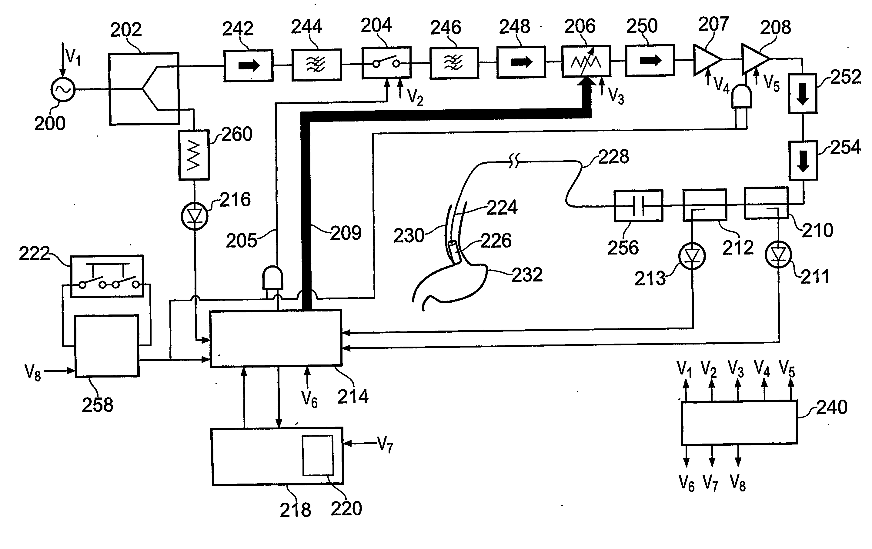
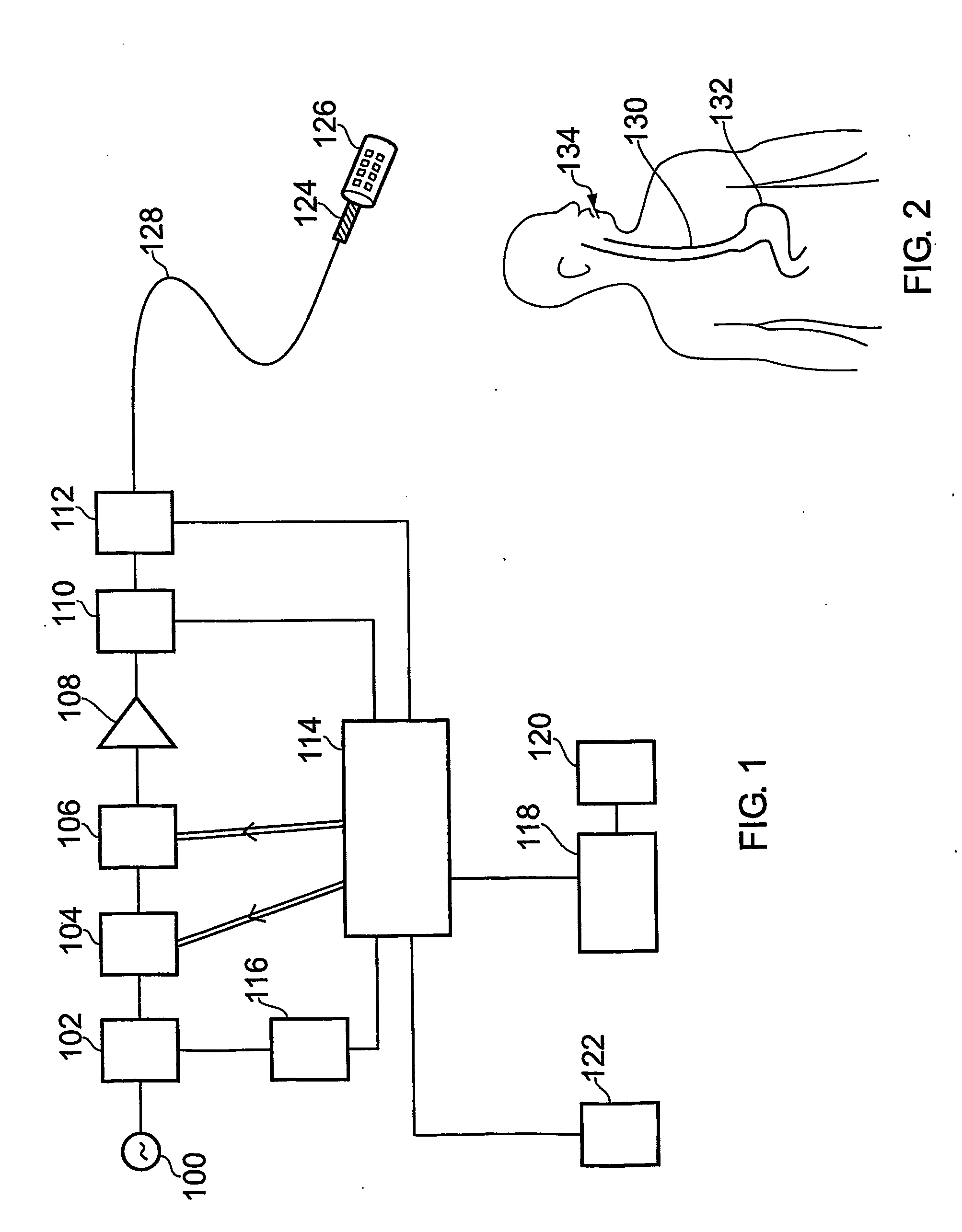
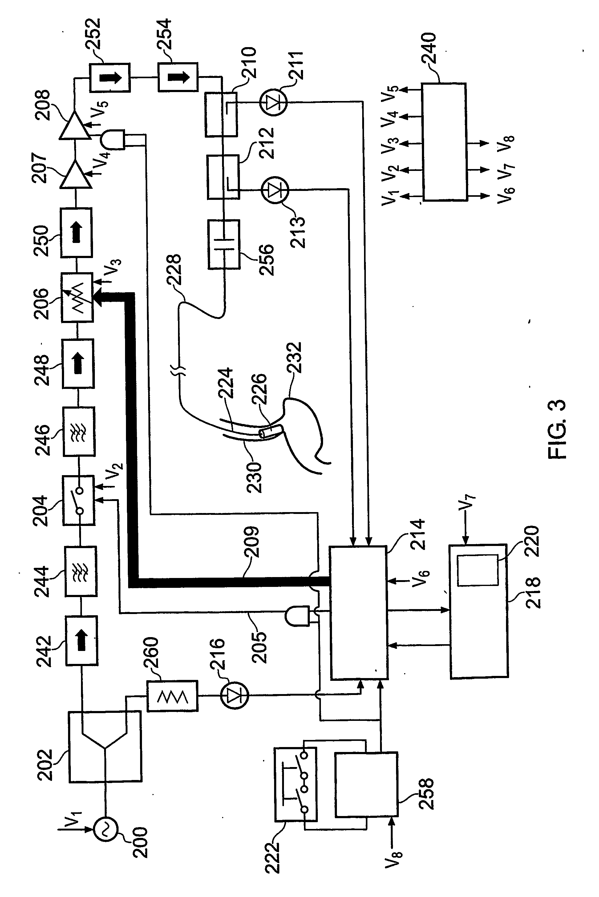
[0134]Firstly, an overview of an embodiment of the whole treatment system will be given, with reference to FIGS. 1 to 3.

[0135]FIG. 1 illustrates the basic structure of the apparatus for treating the oesophageal wall. A stable microwave signal is produced by a microwave source 100. This signal is split into two by splitter 102.

[0136]One part of the split signal is sent to a monitor 116 which is configured to check for low level power coming out of the stable source 100 i.e. if the power level is below a threshold value, set for valid instrument operation, then an error condition will be flagged up. The results of the check by monitor 116 are provided to microprocessor 114, which is arranged to control the operation of the apparatus, and can stop treatment if the monitor 116 detects something wrong with the signal provided to it.

[0137]The other part of the split signal is used for treatment. It is firstly sent to a signal modulator 1...


PUM


Abstract

A probe and associated apparatus for treating oesophageal tissue with microwave radiation (e.g. radiation having a frequency of 5-60 GHz) are disclosed. The probe comprises a flexible substrate that expands and retracts between an access configuration, e.g. suitable for insertion through an endoscope, and a treatment configuration in which radiating elements, e.g. conducting patches, monopole antennas, slots in a conducting strip or the like, are brought into close proximity with tissue to be treated. The radiating elements are arranged to emit a substantially uniform electromagnetic field with a suitable penetration depth into the tissue. The apparatus can monitor and control the power delivered from the probe into tissue. A method of hollow tube, e.g. oesophageal, pathological treatment and a device for opening and closing the probe are also disclosed.

Description

TECHNICAL FIELD[0001]This invention relates to apparatus for and methods of treating tissue using thermal energy derived from microwave radiation. For example, it relates to a technique of causing tissue necrosis (thermal damage) and / or tissue ablation by exposing tissue to radiation with a frequency in the range of 5 to 60 GHz.[0002]The present invention is particularly aimed at treatment of the oesophagus (also known as the esophagus or gullet), e.g. to treat the conditions known as gastro-oesophageal reflux and Barrett's oesophagus. Although the present application is framed around this use, it may also provide a means of treating other medical conditions that are accessible by insertion of a treatment instrument through a natural orifice, (e.g. mouth, nose, anus or urethra). It may also be applicable to treatment in open surgical procedures.BACKGROUND TO THE INVENTION[0003]The oesophagus is the muscular tube that carries food from the mouth to the stomach and is lined by cells s...

Claims


Application Information

Patent Timeline
Patent Type & Authority Applications(United States)
IPC IPC(8): A61B18/18
CPCA61B18/18A61B18/1815A61B2018/1807
Inventor HANCOCK, CHRISTOPHER PAULWHITE, MALCOLMWALL, PETER
Owner MEDICAL DEVICE INNOVATIONS
Why Eureka
Try Eureka