Hydraulic Suspension System for Work Vehicle

a suspension system and work vehicle technology, applied in the field of suspension systems, can solve the problems of durability disadvantage of the suspension reference position variation mechanism, and achieve the effect of reducing the operative load and favorable conditions pertaining to durability

Active Publication Date: 2010-07-01
KUBOTA LTD
View PDF2 Cites 11 Cited by
  • Summary
  • Abstract
  • Description
  • Claims
  • Application Information

AI Technical Summary

Benefits of technology

[0008]The present invention is a suspension system of a work vehicle, the object of which is to reduce the operative load of the suspension reference position variation mechanism and to create favorable conditions pertaining to durability.

Problems solved by technology

Specifically, every time the suspension mechanism operates and the suspension stroke position of the suspension mechanism deviates upward or downward of the vehicle body from the target range, the operative frequency of the suspension reference position variation mechanism is extremely high when the suspension reference position variation mechanism operates, and the suspension reference position variation mechanism has a disadvantage in terms of durability.

Method used


Image

  • Hydraulic Suspension System for Work Vehicle
  • Hydraulic Suspension System for Work Vehicle
  • Hydraulic Suspension System for Work Vehicle

Examples


Embodiment Construction

[0029]The preferred embodiments of the present invention are described hereinbelow with reference to the accompanying drawings. The characteristics of one embodiment can be combined with the characteristics of another embodiment, and such combinations are included within the scope of the present invention as long as there are no discrepancies.

[0030]Examples of the present invention are described hereinbelow with reference to the drawings.

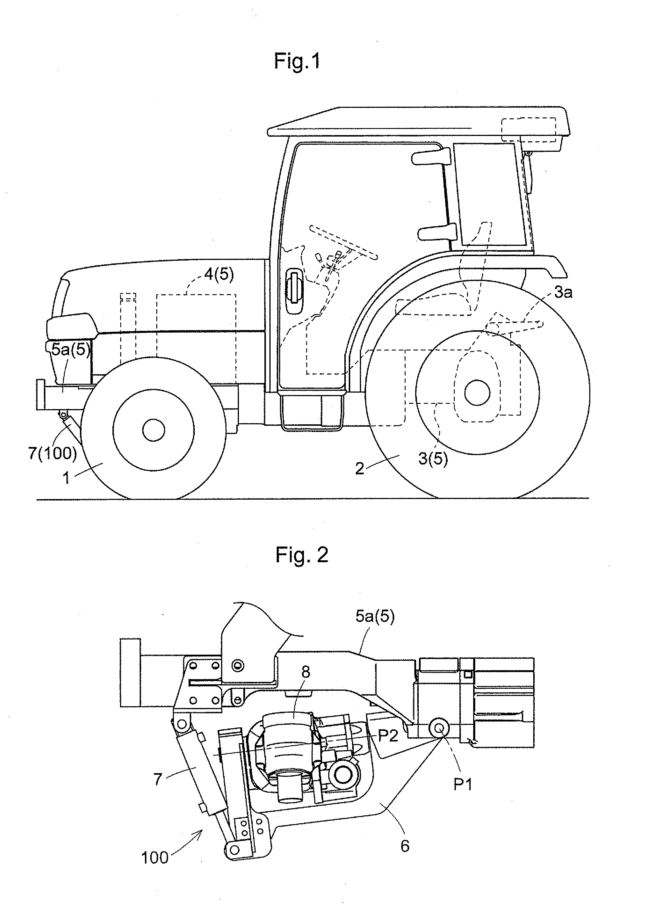
[0031]A tractor, given as an example of a work vehicle, is configured comprising front wheels 1, 1 as a pair of left and right travel devices and a pair of left and right rear wheels 2, 2, as shown in FIG. 1.

[0032]A traveling vehicle body 5 of the tractor comprises an engine 4, a transmission case 3 linked to the rear part of the engine 4, and a front wheel support frame 5a linked to the bottom part of the engine 4 so as to support the front wheels, as shown in FIG. 1. The traveling vehicle body 5 comprises lift arms 3a mounted in a vertically swing...


PUM


Abstract

The hydraulic suspension system comprises a suspension mechanism (100) for a traveling vehicle body, a suspension reference position variation mechanism (18) for varying a reference position of a suspension stroke of the suspension mechanism, and a stopped state detector (58) for detecting a state in which operation of the suspension mechanism (100) has stopped. The control management unit (60) controls the suspension reference position variation mechanism (18) so that when operation of the suspension mechanism (100) is detected by the stopped state detector (58) to be in a stopped state, the operation of the suspension mechanism (100) moves toward a target range, in preference to control based on a suspension stroke position obtained from a suspension stroke position sensor (37).

Description

BACKGROUND OF THE INVENTION[0001]1. Field of the Invention[0002]The present invention relates to a suspension system for a tractor or another work vehicle.[0003]2. Description of the Related Art[0004]Among tractors, which are an example of a work vehicle, there are those which comprise a suspension mechanism in the front wheels, such as is disclosed in U.S. Pat. No. 6,145,859, for example. A suspension mechanism generally acts in rising and falling motions in accordance with unevenness in the ground surface, whereby the unevenness in the ground is absorbed and the ride is made more comfortable.[0005]Worked ground on which the work vehicle travels has much unevenness in comparison with paved roads, and the work vehicle is often equipped with an implement, which causes the suspension stroke position of the suspension mechanism to deviate upward or downward of the vehicle body from a preset target range (when the suspension stroke position of the suspension mechanism is positioned in t...

Claims


Application Information

Patent Timeline
Patent Type & Authority Applications(United States)
IPC IPC(8): G06F19/00B60G11/26B60G17/016
CPCB60G9/00B60G9/02B60G11/265B60G17/015B60G2300/082B60G2400/252B60G2400/5122B60G2500/30B60G2500/322B60G17/0152B60G17/016B60G2500/114B60G2800/16
Inventor IWAMI, KENICHIHAYASHI, SHIGEKIHAYASHI, ATSUSHIMATSUZAKI, AKIHIROYAZAKI, TOSHIMITSUOKABE, NOBUYUKI
Owner KUBOTA LTD
Why Eureka
Try Eureka