Phase error detection device, phase error detecting method, integrated circuit and optical disc device

a phase error detection and phase error detection technology, applied in the direction of instruments, recording signal processing, coding, etc., can solve the problems of increasing the delay time, affecting and the use of the viterbi decoding method requires many computing operations, so as to achieve the effect of improving the stability of pll

Active Publication Date: 2010-07-01
PANASONIC SEMICON SOLUTIONS CO LTD
View PDF15 Cites 3 Cited by
  • Summary
  • Abstract
  • Description
  • Claims
  • Application Information

AI Technical Summary

Benefits of technology

[0009]It is an object of the present invention to provide a phase error detection device, a phase error detecting method, an integrated circuit and an optical disc device, that allow detection of a phase error exceeding ±180° even when a frequency error occurs and also allow improvement in stability of PLL.

Problems solved by technology

A reliable phase error can not be extracted from a 2T signal portion by a conventional phase error detecting method for detecting a zero-cross point.
However, the use of the Viterbi decoding method requires much computing operations.
However, frequent use of pipeline processing causes increase of a delay time during which a phase error is fed back.
The increase of such a delay results in a possibility that PLL becomes unstable.
Consequently, it takes much time to achieve phase synchronization, and this disadvantage causes a problem that the PLL becomes deteriorated in stability.

Method used


Image

  • Phase error detection device, phase error detecting method, integrated circuit and optical disc device
  • Phase error detection device, phase error detecting method, integrated circuit and optical disc device
  • Phase error detection device, phase error detecting method, integrated circuit and optical disc device

Examples


first embodiment

[0039]A phase error detection device, a phase error detecting method, an integrated circuit and an optical disc device according to a first embodiment of the present invention will be described below with reference to FIG. 1 through FIG. 12.

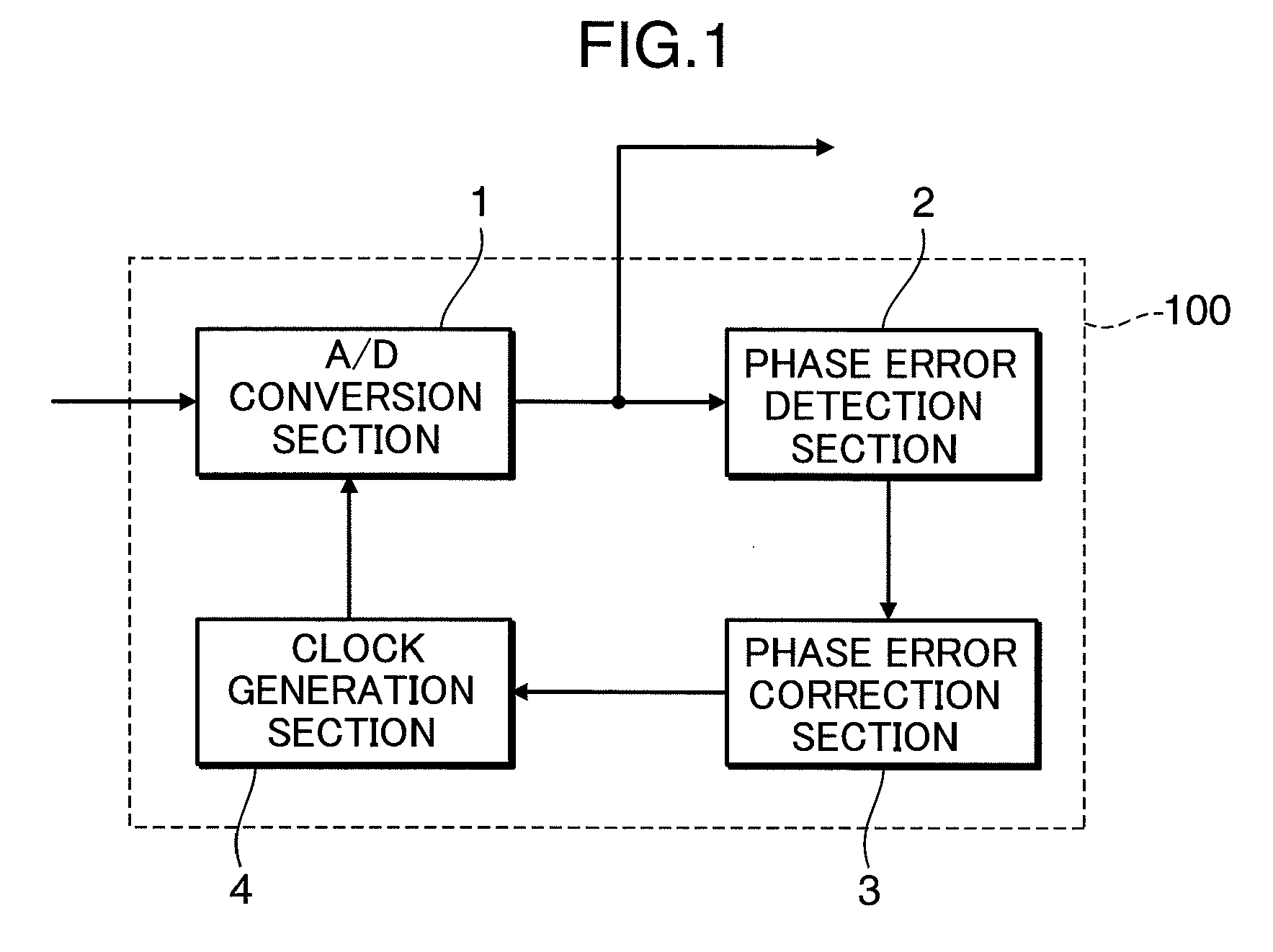
[0040]FIG. 1 is a block diagram showing a schematic configuration of a PLL section 100 to which the phase error detection device according to the present embodiment is applied. As shown in FIG. 1, the PLL section 100 includes an A / D conversion section 1, a phase error detection section 2 (phase error generation section), a phase error correction section 3 and a clock generation section 4. Herein, the phase error detection section 2 and the phase error correction section 3 constitute the phase error detection device according to the present embodiment.

[0041]The A / D conversion section 1 performs A / D conversion on a reproduction signal to be input thereto, in accordance with a clock (a sampling clock) from the clock generation section 4 to generate ...

second embodiment

[0073]A second embodiment of the present invention will be described below with reference to FIG. 13 through FIG. 15.

[0074]In the present embodiment, one example of a phase error detecting method to be used in the present invention will be described.

[0075]FIG. 13 is a block diagram showing a configuration of a phase error detection section 2 (also see FIG. 1) according to the present embodiment. As shown in FIG. 13, the phase error detection section 2 includes a waveform equalization section 22, a binarization section 23 and a phase error computing section 24.

[0076]The waveform equalization section 22 equalizes a waveform of a digital reproduction signal generated by an A / D conversion section 1 (see FIG. 1) to generate a digital equalization signal 10. In the present embodiment, the waveform equalization section 22 generates the digital equalization signal 10 by equalizing the digital reproduction signal such that the digital equalization signal 10 has a PR (1, 2, 2, 2, 1) equalizat...

third embodiment

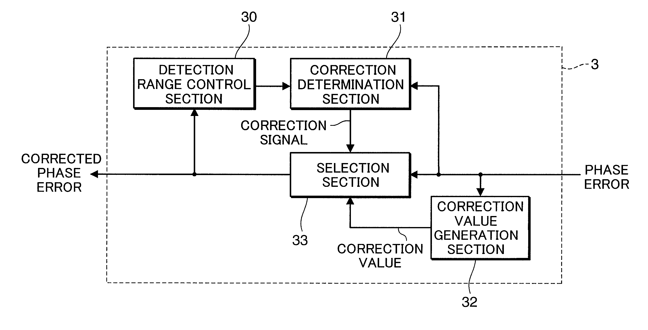
[0105]A method for correcting a phase error according to a third embodiment of the present invention will be described below with reference to FIG. 18 through FIG. 21.

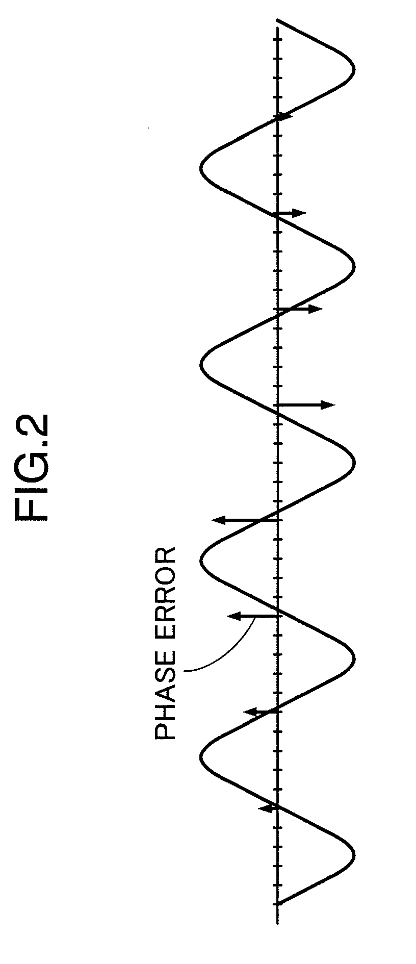
[0106]Erroneous binarization occurs at a portion where a polarity of a phase error is inverted. As shown in FIG. 19, for example, in a case where a clock to be generated by a clock generation section 56 is slightly higher in frequency than a 5T single signal, a result of binarization takes a value of 6T at the portion where the polarity of the phase error is inverted. As shown in FIG. 20, if the result of binarization is corrected to take a value of 5T, a phase advance can be detected continuously.

[0107]FIG. 18 is a block diagram showing a configuration of a PLL section 200 according to the present embodiment. As shown in FIG. 18, the PLL section 200 according to the present embodiment includes an A / D conversion section 51, a waveform equalization section 52, a binarization section 53, a phase error computing section 5...


PUM


Abstract

A phase error detection device detects a phase error, based on an output from an A/D conversion section that performs A/D conversion on an analog input signal in accordance with a sampling clock to generate a digital reproduction signal. The phase error detection device includes a phase error generation section that generates the phase error from the output from the A/D conversion section, and a phase error correction section that corrects the phase error. Herein, the phase error correction section determines a phase error detection range from past phase errors and, when the phase error generated by the phase error generation section is out of the phase error detection range, corrects the phase error.

Description

BACKGROUND OF THE INVENTION[0001]1. Field of the Invention[0002]The present invention relates to a phase error detection device, a phase error detecting method, an integrated circuit and an optical disc device each applied to PLL (Phase Locked Loop) for generating a clock brought into phase synchronization with a reproduction signal in order to detect a phase error.[0003]2. Description of the Background Art[0004]As the density of optical discs increases from CDs (Compact Discs) to DVDs (Digital Versatile Discs) and, further to BDs (Blu-ray Discs), such signal processing method as PRML (Partial Response Maximum Likelihood) has become popular. For example, PR (1, 2, 2, 1) ML is employed for a BD with a recording capacity of 25 GB per layer and PR (1, 2, 2, 2, 1) ML is employed for a BD with a recording capacity of 33.3 GB per layer (e.g., refer to “Illustrated Blu-ray Disc Reading Book”, Ohmsha).[0005]In PR (1, 2, 2, 2, 1), as shown in FIG. 25, a signal level continuously takes a valu...

Claims


Application Information

Patent Timeline
Patent Type & Authority Applications(United States)
IPC IPC(8): G06F11/07
CPCG11B20/10009G11B20/10037G11B20/10046G11B20/1012G11B20/10212G11B20/10222G11B20/10425
Inventor KIMURA, NAOHIRO
Owner PANASONIC SEMICON SOLUTIONS CO LTD
Why Eureka
Try Eureka