Scanning probe microscope capable of measuring samples having overhang structure

Active Publication Date: 2010-07-01
PARK SYST CORP
View PDF4 Cites 6 Cited by
  • Summary
  • Abstract
  • Description
  • Claims
  • Application Information

AI Technical Summary

Benefits of technology

[0009]One or more embodiments of the present invention provide a scanning probe microscope which precisely analyzes characteristics of samples having an overhang surface structure.
[0019]Further embodiments of the present invention provide a scanning probe microscope that can tilt the scanning direction of a z-scanner by a precise amount and with high repeatability.

Problems solved by technology

However, in the case of a conventional scanning probe microscope, there is a problem in that the shape of a surface of a sample or an electrical characteristic of the sample cannot be precisely analyzed on a specific surface shape of the sample.
However, if a sample has an overhang structure illustrated in FIG. 3A, correct data related to the sample cannot be obtained using the conventional scanning probe microscope.
However, when using the probe 10, it is not easy to manufacture the probe 10.
Excessive costs are required for its manufacture and the yield thereof is also low.
In addition, since the probe 10 manufactured in such a way is not sharper than a conventional probe, there is a problem in that precise data related to a fine surface shape of nano-scale cannot be obtained.

Method used


Image

  • Scanning probe microscope capable of measuring samples having overhang structure
  • Scanning probe microscope capable of measuring samples having overhang structure
  • Scanning probe microscope capable of measuring samples having overhang structure

Examples


Embodiment Construction

[0049]The present invention will now be described more fully with reference to the accompanying drawings, in which exemplary embodiments of the invention are shown.

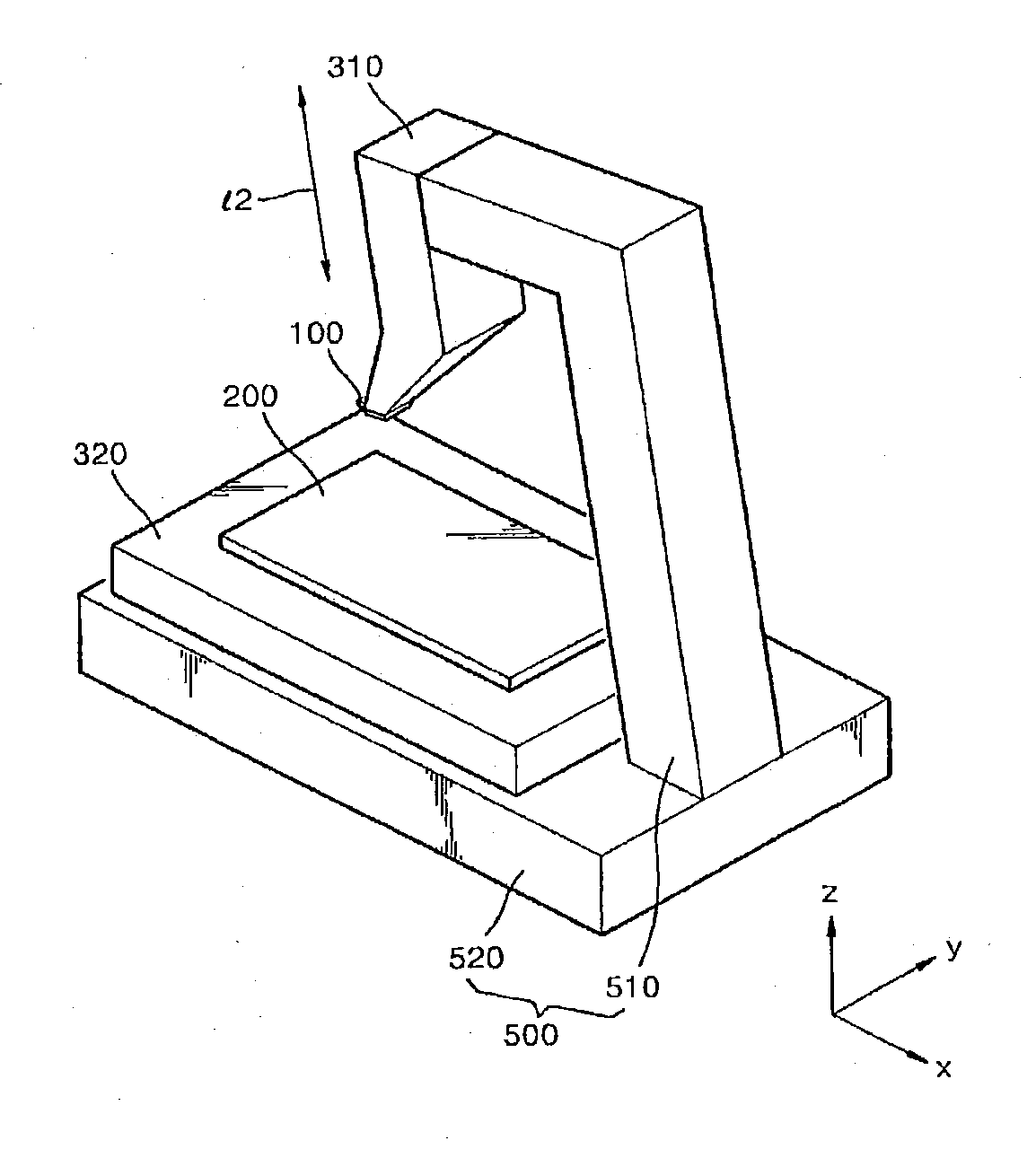
[0050]FIG. 5 is a schematic perspective view of a scanning probe microscope according to an embodiment of the present invention. Referring to FIG. 5, the scanning probe microscope includes a first probe 100, a first scanner 310, and a second scanner 320. Of course, if necessary, the scanning probe microscope may further include a frame 500 having a first frame 510 for supporting the first scanner 310 and a second frame 520 for supporting the second scanner 320, as illustrated in FIG. 5.

[0051]The first scanner 310 changes the position of the first probe 100 along a straight line I2, and the second scanner 320 changes the position of a sample 200 in a plane (an xy-plane). In this case, the straight line I2 in which the position of the first probe 100 is changed using the first scanner 310 is not perpendicular to the plane (...


PUM


Abstract

A scanning probe microscope tilts the scanning direction of a z-scanner by a precise amount and with high repeatability using a movable assembly that rotates the scanning direction of the z-scanner with respect to the sample plane. The movable assembly is moved along a curved guide by a rack-and-pinion drive system and has grooves that engage with corresponding ceramic balls formed on a stationary frame to precisely position the movable assembly at predefined locations along the curved guide. The grooves are urged against the ceramic balls via a spring force and, prior to movement of the movable assembly, a pneumatic force is applied to overcome the spring force and disengage the grooves from the ceramic balls.

Description

CROSS-REFERENCE TO RELATED APPLICATION(S)[0001]This application is a continuation-in-part of U.S. patent application Ser. No. 12 / 393,293, filed Feb. 26, 2009, which is a continuation-in-part of U.S. patent application Ser. No. 11 / 601,144, filed Nov. 17, 2006, now U.S. Pat. No. 7,644,447.BACKGROUND OF THE INVENTION[0002]Embodiments of the present invention generally relate to a to a scanning probe microscope (SPM), and more particularly, to an SPM which precisely analyzes characteristics of samples having an overhang surface structure.[0003]Scanning probe microscopes (SPMs) have nano-scale resolution in order to show the shape of a surface of a sample or an electrical characteristic of the sample as an image. SPMs include atomic force microscopes (AFMs), magnetic force microscopes (MFMs), and scanning capacitance microscopes (SCMs). SPMs are used to analyze the shape of a surface of a sample or an electrical characteristic of the sample by moving a tip of a probe in contact with the ...

Claims


Application Information

Patent Timeline
IPC IPC(8): G01Q10/00
CPCB82Y35/00G01Q10/04Y10S977/851Y10S977/872
Inventor PARK, SANG-ILCHUNG, SANG HANAHN, BYOUNG-WOON
Owner PARK SYST CORP
Why Eureka
Try Eureka