
Shower base apparatus

Active Publication Date: 2010-07-08
NOBLE CO LTD
View PDF28 Cites 22 Cited by
  • Summary
  • Abstract
  • Description
  • Claims
  • Application Information

AI Technical Summary

Benefits of technology

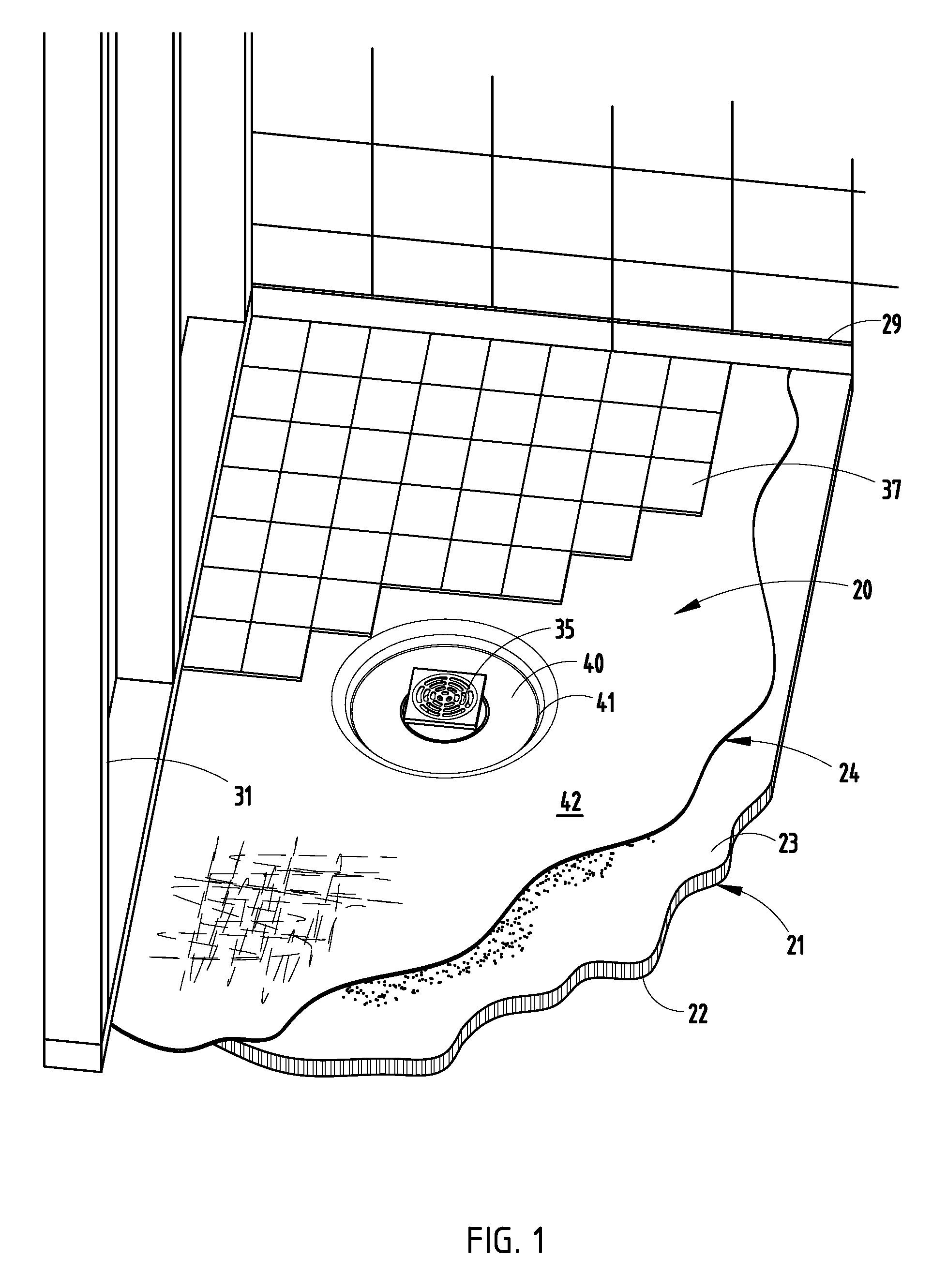
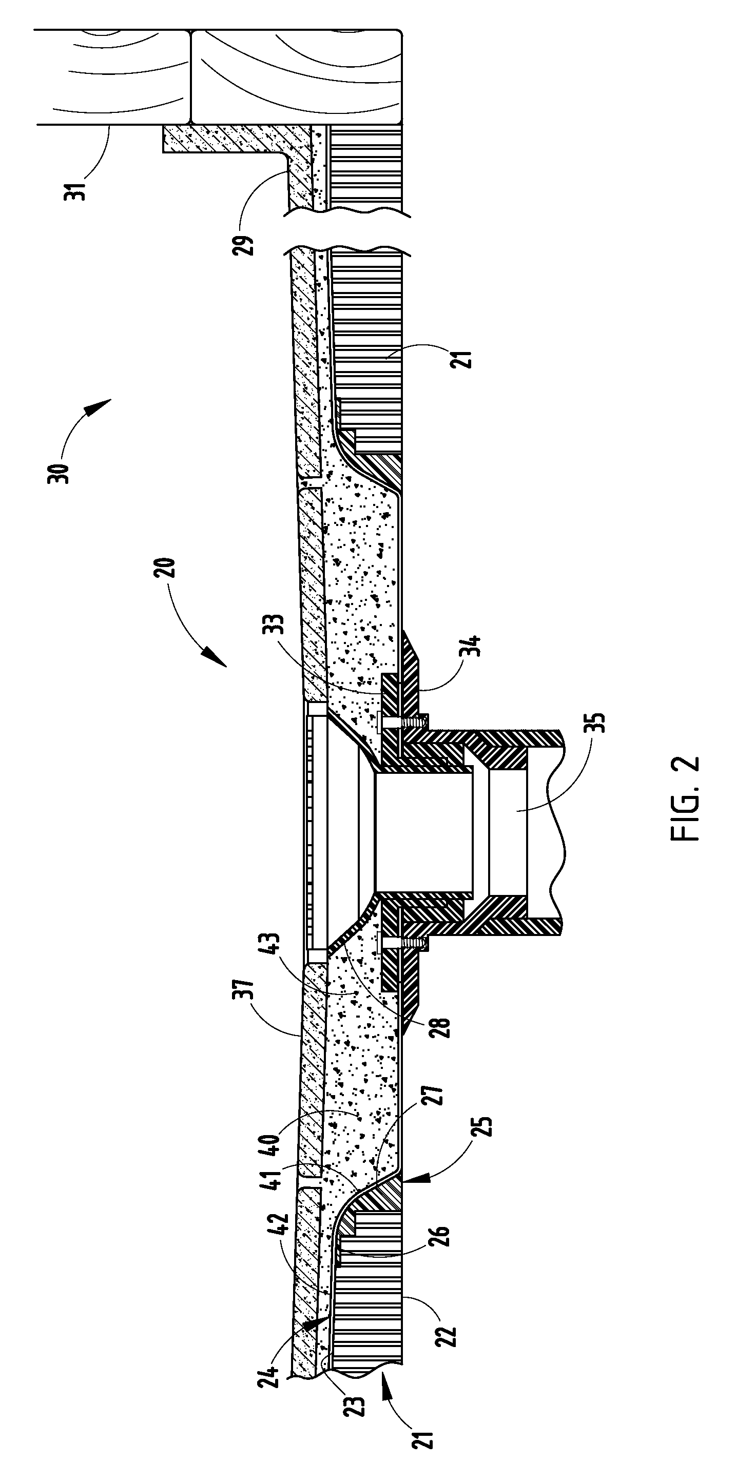
[0008]A manufactured shower base assembly includes a thermoplastic honeycomb structure with a spun bond polyester fabric bonded to its base surface. The upper surface of the honeycomb structure is contoured to a desired slope and drain opening configuration, and includes a thermoplastic pre-formed thermoplastic waterproof membrane integrally bonded to its top surface, the membrane being contoured to conform to a shape of the honeycomb structure. A structural ring is utilized to provide added structure around the drain opening. The configuration allows for adjustment when placing / installing the shower base in relation to walls of the shower enclosure and to a floor drain in the shower enclosure, and further allows for attachment to any common clamping ring style drain, yet provides for efficient and quick installation with minimization of skilled labor time.

Problems solved by technology

However, these types of shower pans were / are difficult and time-consuming to construct, and they were / are prone to leaking.
Although this improved the integrity of the waterproofing, it still requires skilled labor to install the mortar bed on the pan.
It also requires curing of the mortar bed prior to installation of the tile or stone, which takes time and potentially leads to inefficient use of skilled manpower due to the necessity of more than one visit by the skilled workers to the installations.
As land and infrastructure costs have increased, residential homes and condominiums of multi-floor design have also increased.
However, this increased density has created problems in the area of sound transmission between floors and ceilings of units above and below.
The sound created by normal activity is transmitted through floors and is typically referred to as “Impact Sound.” Bathrooms tend to be difficult areas to reduce the level of impact sound transmission to the unit below since a majority of bathroom areas are covered with ceramic tile or natural stone where transmission of sound through the floor becomes an issue.
Since virtually all sound reduction materials are installed under the finish flooring, the area under a shower floor is not able to be isolated.
Also, many bathroom “furniture” and structural articles, such as ceramic and / or metal toilets, tubs, sinks, countertops and pipes, can be sound generators and / or sound carriers, making it difficult to achieve a satisfactorily “quiet” bathroom area.
However, the responsibility for the waterproof integrity and flood testing of the installation most often lies on the plumber.
This requires coordination of skilled trades, which can lead to inefficiencies and hence higher costs during installation.
However, the existing known pre-manufactured shower bases and trays do not permit adjustment in a back-to-front direction, nor in a side-to-side direction, nor diagonally, in order to match drain (and wall) locations.
Floor drains also cannot be adjusted once rough-in piping is set during early stages of construction.
Thus, in known systems, the floor drain must be precisely located in the shower floor relative to shower walls during building construction, and the location of the drain opening in pre-manufactured shower bases must be accurately cut to match, which is very difficult to do on a consistent basis in “real world” building constructions.
Further, pre-manufactured shower bases and trays often still require repeated trips back to the installation site by skilled trades, thus still resulting in greater installation costs than desired.
Still further, grout and tile are relatively brittle and very sensitive to any deflection, which leads to cracking when the floor flexes or is stressed, which in turn leads to water leak problems.
Yet some pre-manufactured shower bases arguably provide only marginal rigidity and stability.

Method used


Image

  • Shower base apparatus
  • Shower base apparatus
  • Shower base apparatus

Examples


Embodiment Construction

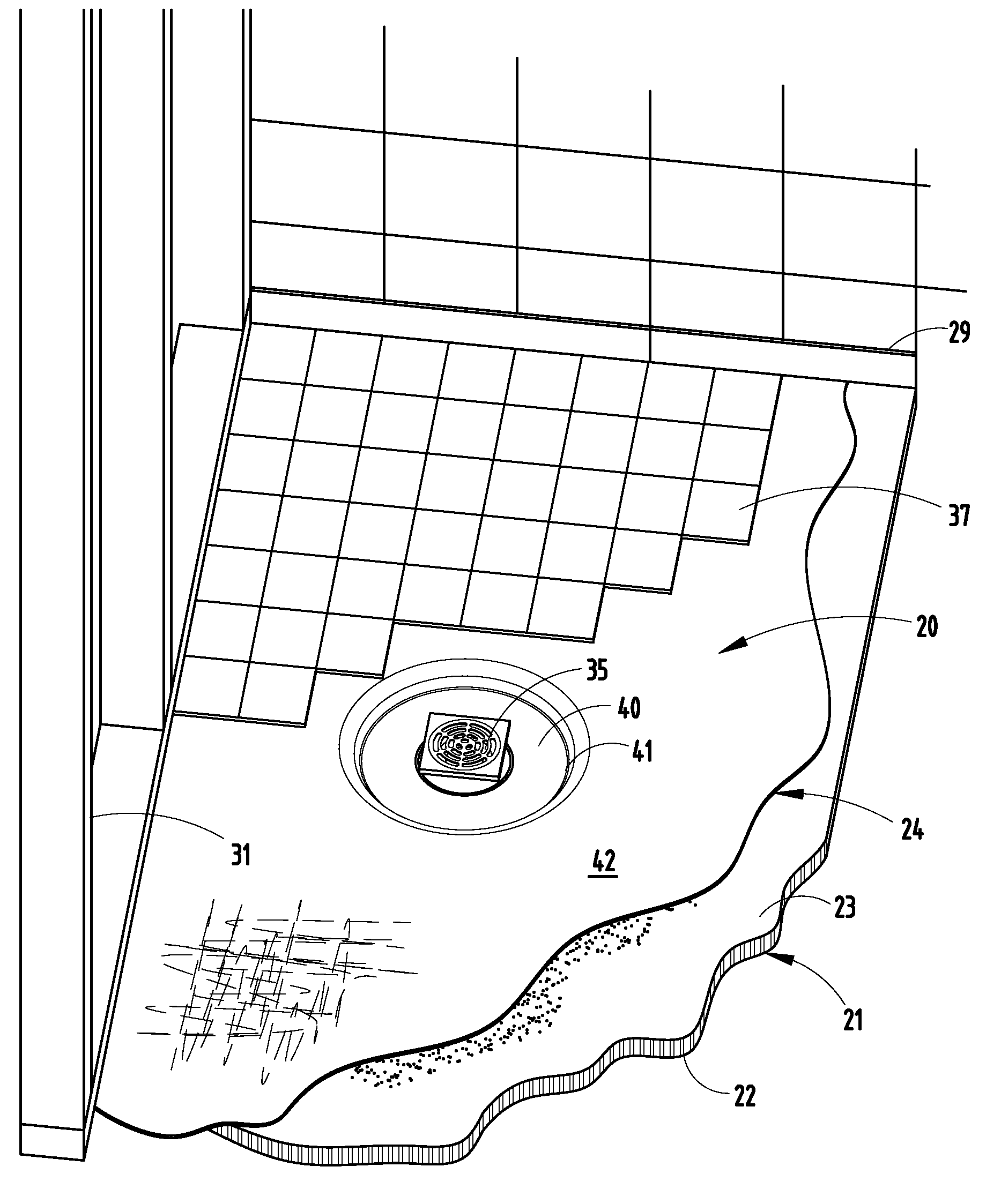
[0020]A manufactured shower base assembly 20 (FIG. 1) includes a thermoplastic honeycomb structure 21 with a spun bond polyester fabric 22 bonded to its base (bottom) surface. The illustrated polyester fabric has a typical tensile strength of 175 psi. The upper surface 23 of the honeycomb structure is contoured to a desired slope and drain opening configuration, and includes a thermoplastic pre-formed thermoplastic waterproof membrane 24 supported on and potentially integrally bonded to its upper surface 23. The waterproof membrane 24 is contoured to conform to a shape of the upper surface 23 of the honeycomb structure 21. A molded polymeric structural ring 25 includes a perimeter flange 26 that fits into a mating recess in the upper surface 23 of the honeycomb structure 21 and further includes a downwardly extending sleeve 27 that extends toward the drain opening 28. The structural ring 25 is utilized to provide added structure to the honeycomb structure 21 around the drain opening...


PUM

PropertyMeasurementUnit
Compressive strengthaaaaaaaaaa
Thicknessaaaaaaaaaa
Structureaaaaaaaaaa

Abstract

A manufactured shower base assembly includes a thermoplastic honeycomb structure with a spun bond polyester fabric bonded to its base surface. The upper surface of the honeycomb structure is contoured to a desired slope and drain opening configuration, and includes a thermoplastic pre-formed thermoplastic waterproof membrane integrally bonded to its top surface, the membrane being contoured to conform to a shape of the honeycomb structure. A structural ring is utilized to provide added structure around the drain opening. The configuration allows for adjustment when placing / installing the shower base in relation to walls of the shower enclosure and to a floor drain in the shower enclosure, and further allows for attachment to any common clamping ring style drain, and provides for efficient and quick installation with minimization of skilled labor time.

Description

[0001]This application claims benefit under 35 U.S.C. §119(e) of provisional application Ser. No. 61 / 142,947, filed Jan. 7, 2009, entitled SHOWER BASE APPARATUS, the entire contents of which are incorporated herein in their entirety.BACKGROUND[0002]The present invention relates to a prefabricated shower base assembly for tile and stone applications in showers.[0003]Tile and stone covered showers have been used for many years; however, construction methods for constructing showers and wet areas have changed dramatically such that construction of a sub-base is necessary to provide support for tile or stone floor surfaces. For example, waterproofing beneath the tile or stone is particularly necessary in multi-story constructions with living space beneath the shower area. This led to the creation / use of waterproof envelopes / barriers under the tile or stone, known as “shower pans.” Early shower pans were constructed of copper, sheet metal or sheet lead, and were clamped to the drain typi...

Claims


Application Information

Patent Timeline
IPC IPC(8): A47K3/00B23P17/04
CPCA47K3/40A47K3/405Y10T29/4998
Inventor KIK, SR., PAUL S.KIK, JR., PAUL S.WADAGA, JAMES A.
Owner NOBLE CO LTD
Learn More